It's not bigger dies. it's two separate LM3886 chips in one package.To be honest, I can't tell any significant audible differences in the two chips. That's because the 4780 is simply 2 x 3886s on the a bigger die.
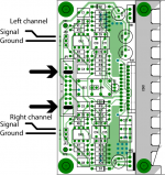
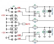
I think you will discover why when you start soldering. I recommend that you take a look at the schematics. There you will see that +INL, -INL, +INR and +INR shall be connected in a certain way. You must always have two jumpers so also connecting the input wires there is a bit hard.I'm a bit confused about the input connection in JP2 and JP3, though.
Why all of you guys soldered jumper pins here? Can't you just solder the inputs directly to these points?
Thanks, clog. The image you posted showed me how I'll connect the input wires.
I was going to replicate the connections from your build anyway.
But I always try to understand things first.
The schematics and the text explanation from PD's documents are still unclear to me.
I'll just follow the image and I'm sure it will sound great.
I'll proudly post pictures as soon as the components arrive.
Attachments
Hi clog. I'm also building a PA03. Any chance that you used a BLOCK RTE transfomer.
If yes, is the wiring on your image (on page 3 in this thread) the correct wiring of the transformer
3 -> Black
4 -> Red
5 -> Orange
6 -> Grey
If yes, is the wiring on your image (on page 3 in this thread) the correct wiring of the transformer
3 -> Black
4 -> Red
5 -> Orange
6 -> Grey
IMHO you can solder the input signal wires directly to the ports, but i guess it adds more flexibility to play around with the configuration if you use the pins and a propper connector to connect the signal cables.
Why all of you guys soldered jumper pins here? Can't you just solder the inputs directly to these points?
Hi clog. I'm also building a PA03. Any chance that you used a BLOCK RTE transfomer.
If yes, is the wiring on your image (on page 3 in this thread) the correct wiring of the transformer
3 -> Black
4 -> Red
5 -> Orange
6 -> Grey
Yes this is a Block transformer and the wiring you see on the first picture in page 3 is the correct wiring. As Peranders told me “one winding with dot to ground and the other winding "no dot" to ground”. Also check the enclosed pdf file.
Attachments
thanks, i thought so too. what i ended up connecting them in the order from the BLOCK RTE data sheet as i wanted to do it initially. your post on page 3 has made me unsure, where you mentioned someone bricking his rectifiers.
3 -> red
4 -> black .
5 -> grey
6 -> orange .
voltages look good so far. just waiting for the heatsink, so i can finish them electrically and get some sound out of it.
next steps -> chassis, diy speakers and preamp
3 -> red
4 -> black .
5 -> grey
6 -> orange .
voltages look good so far. just waiting for the heatsink, so i can finish them electrically and get some sound out of it.
next steps -> chassis, diy speakers and preamp
Yesterday i finished the heatsink and was ready to test my PA03.
Without any input signal and load it gets pretty hot and requires around 110W. No relay is switching.
TP1 -> 11.99V
TP2 -> -12.01V
TP3 -> -0.04V
TP4 -> -29,6V
My first thought is that i shortened something aroung th LM4780. Any clues where to look for my mistake are highly appreciated!
Without any input signal and load it gets pretty hot and requires around 110W. No relay is switching.
TP1 -> 11.99V
TP2 -> -12.01V
TP3 -> -0.04V
TP4 -> -29,6V
My first thought is that i shortened something aroung th LM4780. Any clues where to look for my mistake are highly appreciated!
Ragerino, to help you better I think we need some detailed pictures from front and solder side of the pcb. Remember that if the LM4780 is not isolated from the heatsink, there is negative DC on the sink. Furthermore one of the excellent tips I got here is the use of a bulb tester to prevent things from burning at first power on and subsequent testing. Also check the board for correct placement of components, cold solder joints and solder bridges.
Did the bulb light up, or glow dimmly, or remain completely off?
i didn't do the bulb test.
Ragerino, to help you better I think we need some detailed pictures from front and solder side of the pcb. Remember that if the LM4780 is not isolated from the heatsink, there is negative DC on the sink. Furthermore one of the excellent tips I got here is the use of a bulb tester to prevent things from burning at first power on and subsequent testing. Also check the board for correct placement of components, cold solder joints and solder bridges.
this website says "The heatsink is floating which means that the LM4780 doesn't need any insulation but heat compound is need to ensure proper heat transfer."
see -> sjostromaudio.com
Here's some photos of my PA03 -> Album
Your chip could well be broken now.
I get always the same voltages. Could it be that the 4780 was broken from the start?
Both my Opamps have 36mV DC on pin 6
update: i just ordered a new lm4780ta on ebay
Last edited:
4780 are now discontinued.
Ebay could be anything, except a genuine 4780.
Where did you get your existing one from?
Ebay could be anything, except a genuine 4780.
Where did you get your existing one from?
Did you measure to check that the heatsink really was isolated, both from the chassis and from the PSU?this website says "The heatsink is floating which means that the LM4780 doesn't need any insulation but heat compound is need to ensure proper heat transfer."
see -> sjostromaudio.com
Here's some photos of my PA03 -> Album
If your LM4780 was genuine I doubt if it was defective before, but if it was originally from ebay :😡😡😡😡
Ragerino looking at your pictures there's something I noticed. When I solder a component I like to see that a little bit of solder is flowing through the vias to the other side of the board to prevent having a cold joint. When you for instance look at the left and right pins of your LM on the component side of the board it looks suspect. Perhaps someone with more experience can chime in here.
- Home
- Amplifiers
- Chip Amps
- Newbee build: PA03 amp (LM4780)