Hi again. Seems that I have a clipping problem on the left channel (left when looking straight at the LM4780) of the channels.
Switching inputs (L <-> R) didn't change anything. Same goes for switching OpAmps. Only left channel seems to be clipping.
Song - "Nils Lofgren - Accoustic Live (1997) - Keith don't go".
I wasn't able to see any clipping on my oscilloscope. Any ides how i can measure it? I guess I will need 4 and 8 Ohm High Power resistors.
Hi!
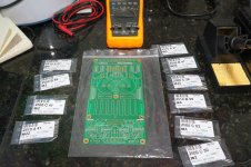
Work in progress here.
Started yesterday evening and very few parts still missing on the board.
Free time gets scarce when you have kids in the house.
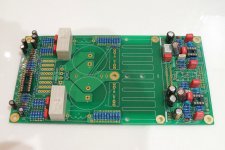
As you can see, I hard wired jumper JP4. Will do the same with the inputs at non inverted mode.
Also, on C11 and C15 I opted for the 47uF electrolytic as recommended by Dudek for normal stereo operation.
On C12 and C13, PD specifies 1nF/500V "kerko", which probably means ceramic.
I used metallized polyester 1nF/100V. Do you guys see any potential problem?
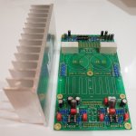
How about the heatsink? I still can't figure out how to attach this heavy piece to the PCB.
Any suggestions?
I'll post more pictures (and questions) as I progress.
Thank you very much!
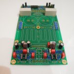
Work in progress here.
Started yesterday evening and very few parts still missing on the board.
Free time gets scarce when you have kids in the house.
As you can see, I hard wired jumper JP4. Will do the same with the inputs at non inverted mode.
Also, on C11 and C15 I opted for the 47uF electrolytic as recommended by Dudek for normal stereo operation.
On C12 and C13, PD specifies 1nF/500V "kerko", which probably means ceramic.
I used metallized polyester 1nF/100V. Do you guys see any potential problem?
How about the heatsink? I still can't figure out how to attach this heavy piece to the PCB.
Any suggestions?
I'll post more pictures (and questions) as I progress.
Thank you very much!
Attachments
How about the heatsink? I still can't figure out how to attach this heavy piece to the PCB.
Any suggestions?
I'll post more pictures (and questions) as I progress.
Thank you very much!
Most people screw the heatsink to the board. There are two holes for that purpose.
.................How about the heatsink? I still can't figure out how to attach this heavy piece to the PCB.
Any suggestions?
I'll post more pictures (and questions) as I progress.
Thank you very much!
The two middle existing holes will be under the narrow fins. Twp more holes out at the ends of the sink but also into the narrow fins. Not much good for that shape of heatsink.Most people screw the heatsink to the board. There are two holes for that purpose.
Tap two 3mm holes into the edge of the heatsink backplate.
Attach using plastic/nylon screws.
Last edited:
Thanks clog and AndrewT for the replies.
Andrew is right, the heat sink base and fins doesn't align with the PCB screws.
I'll attach it to the chassis floor as suggested. But do I have to isolate it with nylon screws? I'm not sure if nylon will give it a tight grip.
Andrew is right, the heat sink base and fins doesn't align with the PCB screws.
I'll attach it to the chassis floor as suggested. But do I have to isolate it with nylon screws? I'm not sure if nylon will give it a tight grip.
Thanks clog and AndrewT for the replies.
Andrew is right, the heat sink base and fins doesn't align with the PCB screws.
I'll attach it to the chassis floor as suggested. But do I have to isolate it with nylon screws? I'm not sure if nylon will give it a tight grip.
I used metal screws with a washer. Just make sure you're not shortening things. If you want to connect the Heatsink to the chassis for better heat distribution, make sure you also isolate electrically the lm4780 chip from the heatsink, otherwise you will have -Vss connected to your chassis.
I used a nonconducting thermal pad for insulation.
Andrew is right, the heat sink base and fins doesn't align with the PCB screws.
The holes in the middle of the heatsink dont need to align with the fins. I guess they are for an alternate way to mount the heatsink. I think you could use a metal plate on top of the heatsink and long screws or a threaded rod.
But I went for the two holes at the edge of the PCB. You will need to drill holes and cut threads into the heatsink for that. I used M3 screws, despite also M4 screws would have fitted. But you will nyways need M3 screws for mounting the voltage regulators and the amp chip. So no need for bigger drills and thread cutters.
To keep things simple just look at the pcb. The heatsink is clearly outlined on the board. To the left and to the right there are mounting holes that correspond with the base plate of your heat sink. Both mounting holes are isolated. I tapped M4 threads in the base of my heat sink and fastened it with steel screws and washers. There is no need for nylon screws and washers. On the contrary it is weakening the connection. Ragerino is right about the LM4780. For better heat transfer you can decide to mount the LM4780 without insulation. That's what I did. But in that case the heat sink is connected to the negative power supply so you be careful. Speaking of heat transfer. At times I played my music almost unbearably loud. The PA03 never tripped the Build in SPIKE protection.
I think you could use a metal plate on top of the heatsink and long screws or a threaded rod.
Very good idea. That's what I'm going to do then. I'll try to brace the heatsink against the PCB using a transverse bar. I hope I can do something visually pleasant.
The heatsink is clearly outlined on the board.
The heatsink that I bought doesn't match the PCB outline.
Thanks!
The heatsink that I bought doesn't match the PCB outline.
I also used a different heat sink, because I didn't want it to have a height of 100 mm which would require an enclosure with an inner height of ~110 mm. I wanted it to be more compact.
Therefore I selected a heat sink with a similar cooling performance which was 160 mm wide, which means I have excess length of 30 mm on both sides. I mounted it with the two bottom screws because this seemed to me to be the best mounting method. I used 3 mm screws with a washer for mounting.
You can find some pictures of my amp in this album -> LINK
I got my heat sink from here -> LINK
Current status is that I'm waiting for the enclosures to arrive so I can finally finish my amp.
The same here. My heatsink was wider too because I couldn't accomodate the height of 100 mm. So no problem, use the two bottom screws into the base plate of your sink.I also used a different heat sink, because I didn't want it to have a height of 100 mm which would require an enclosure with an inner height of ~110 mm. I wanted it to be more compact.
Therefore I selected a heat sink with a similar cooling performance which was 160 mm wide, which means I have excess length of 30 mm on both sides. I mounted it with the two bottom screws because this seemed to me to be the best mounting method. I used 3 mm screws with a washer for mounting.
We all had similar concerns about the enclosure size and the heat sink.
Mine is 160mm wide and 80mm tall.
Ragerino, I usually buy parts from a Berlin based company and next time I'll try the one you linked. Just for a change. Your build looks very nice. Thanks for the tip.
Mine is 160mm wide and 80mm tall.
Ragerino, I usually buy parts from a Berlin based company and next time I'll try the one you linked. Just for a change. Your build looks very nice. Thanks for the tip.
We all had similar concerns about the enclosure size and the heat sink.
Mine is 160mm wide and 80mm tall.
Ragerino, I usually buy parts from a Berlin based company and next time I'll try the one you linked. Just for a change. Your build looks very nice. Thanks for the tip.
Here's what I would suggest to you:
Thanks for the compliment. I appreciate it. My solder points don't look as good as I intended. I had to replace the LM4780. A good tip from my side is, to measure all voltages before you solder the amp-chip.
First you should measure the voltages without the voltage regulators. If everything is fine insert the voltage regulators. My tip here is to mount them on the heat sink first (insulate them from the heat sink). Then mount the heat sink with the voltage regulators and after that solder them to the board.
Measure the voltages. I had a problem with R27 --> I had a floating ground. This might have caused the death of my first LM4780. Measure the voltages aon the opamp before you insert them. After you insert them you can measure if the voltages at the pins of the LM4780 are correct.
After that you can solder the LM4780. Use a magnifier glass to check if you didn't accidentally connect any pins which should not be connected.
Use always the light bulb trick to prevent damage when doing checking the voltages. I didn't do that.
You will like the result! I am very pleased with the sound.
If you have any questions post them here. I am happy to give back the help I received. The folks here are very helpful.
My tip here is to mount them on the heat sink first (insulate them from the heat sink). Then mount the heat sink with the voltage regulators and after that solder them to the board.
I'll try to solder the regulators to the board prior to attaching them to the heat sink. Otherwise I'll have to apply way too much heat to its joints.
Soldering the LM4780 will be the most delicate part of the job. I'll use a fine tip for that purpose.
Thanks.
I think it's a better idea to mount the regulators first at the heatsink and the soldering them. It's no risk to get them overheated.The advantage to mount them first is to minimize mechanical tensions.
Very useful information for a newbie like me.
Just signed up GB for this board and start to read this thread carefully.
Just signed up GB for this board and start to read this thread carefully.
Very useful information for a newbie like me.
Just signed up GB for this board and start to read this thread carefully.
Per Anders, clog and others are most helpful. The community here is fantastic! I will also try to help out if my time allows it.
I can only say the amp sounds fantastic, comes with all bells and whistles and is worth the effort.
I am collecting parts for this project.
Just like to ask if I can use silver mica caps instead of the ceramic NP0 caps listed in the BOM?
Also, does it have to be 500V? Can I use lower voltage like 100V?
Just like to ask if I can use silver mica caps instead of the ceramic NP0 caps listed in the BOM?
Also, does it have to be 500V? Can I use lower voltage like 100V?
the highest voltage rating generally required is a bit in excess of the rail to rail voltage when mains is at it's highest. Many will never be exposed to more than a couple of Volts.
A chipamp running on ±35Vdc supplies would never over voltage a 100V capacitor, unless the amp went into full oscillation where Q can take voltage a bit higher than rail to rail. It's not just a few damaged capacitors that you need to check after that event !
A chipamp running on ±35Vdc supplies would never over voltage a 100V capacitor, unless the amp went into full oscillation where Q can take voltage a bit higher than rail to rail. It's not just a few damaged capacitors that you need to check after that event !
- Home
- Amplifiers
- Chip Amps
- Newbee build: PA03 amp (LM4780)