What to expect here, soundwise ?
If I was a betting man, I would say not as good. I'm typically wrong though 😀
Just from some research, the 741 opamp was one of the first opamps made. I'm sure technology has came quite as way since the 60's.
I swapped mine back to the OPA134s and I can tell a difference. I prefer the OPA134s to the AD843. It seems more detailed while the AD843 almost seemed overly smooth.
There is 12v dc on the PA03 input connector. With a series resistor you can connect a led here.
Hi all
Thanks Clog for starting this thread. It has helping me a lot with my non-inverted stereo PA03 built.
I'm almost done but I have a couple of questions hoping someone could help me with (if you don't mind using your thread Clog).
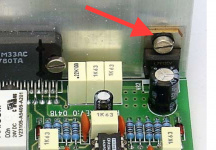
1) In the description Per-Anders website it's mentioned that the voltage regulators 7812 & 7912 must be insulated from the heatsink. I have slip pads but how do I insulate the regulator from the screw that will be attached to the heatsink?
Sjöström Audio - PA03 Pavel Dudek's deLuxe Gainclone
2) I would like to have a potentiometer integrated in the same box. What resistance value should it have or what is recommended? Is 50 kohm OK?
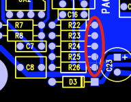
3) Since I'm totally beginner in soldering I made of course a beginner misstake. I've made a joint between the pins of R10 & R11 on the backside of the board. I tried to correct it but it was impossible for me as a beginner. However, I've studied the schematics and according to my understanding it should be OK since the R10 & R11 are connected in parallell. I'm I thinking wrong and should those pins be sperated?
Thanks!
Thanks Clog for starting this thread. It has helping me a lot with my non-inverted stereo PA03 built.
I'm almost done but I have a couple of questions hoping someone could help me with (if you don't mind using your thread Clog).
1) In the description Per-Anders website it's mentioned that the voltage regulators 7812 & 7912 must be insulated from the heatsink. I have slip pads but how do I insulate the regulator from the screw that will be attached to the heatsink?
Sjöström Audio - PA03 Pavel Dudek's deLuxe Gainclone
2) I would like to have a potentiometer integrated in the same box. What resistance value should it have or what is recommended? Is 50 kohm OK?
3) Since I'm totally beginner in soldering I made of course a beginner misstake. I've made a joint between the pins of R10 & R11 on the backside of the board. I tried to correct it but it was impossible for me as a beginner. However, I've studied the schematics and according to my understanding it should be OK since the R10 & R11 are connected in parallell. I'm I thinking wrong and should those pins be sperated?
An externally hosted image should be here but it was not working when we last tested it.
An externally hosted image should be here but it was not working when we last tested it.
Thanks!
If your pot needs to drive a longer interconnect, then a low 5k, or 10k, would be recommended.
Where it has to drive a short cable, then 20k, or 50k, works OK.
For a pot integrated into the power amplifier where the following capacitance can be made to be low, then 50k, or even 100k, works well.
But isolate the wiper from the amplifier with a DC blocking capacitor.
And add an RF attenuation capacitor at the RCA inputs and at the PCB input.
siha:The metal surface of the regulator should not be in any contact with the heatsink. Normally you have a plastic bushing plus a screw when you mount the part.
About the pot: 10-50 kohm and 10 k is better.
About the pot: 10-50 kohm and 10 k is better.
Attachments
Last edited:
Hi all
Thanks Clog for starting this thread. It has helping me a lot with my non-inverted stereo PA03 built.
I'm almost done but I have a couple of questions hoping someone could help me with (if you don't mind using your thread Clog).
1) In the description Per-Anders website it's mentioned that the voltage regulators 7812 & 7912 must be insulated from the heatsink. I have slip pads but how do I insulate the regulator from the screw that will be attached to the heatsink?
Sjöström Audio - PA03 Pavel Dudek's deLuxe Gainclone
2) I would like to have a potentiometer integrated in the same box. What resistance value should it have or what is recommended? Is 50 kohm OK?
3) Since I'm totally beginner in soldering I made of course a beginner misstake. I've made a joint between the pins of R10 & R11 on the backside of the board. I tried to correct it but it was impossible for me as a beginner. However, I've studied the schematics and according to my understanding it should be OK since the R10 & R11 are connected in parallell. I'm I thinking wrong and should those pins be sperated?
An externally hosted image should be here but it was not working when we last tested it.
An externally hosted image should be here but it was not working when we last tested it.
Thanks!
1. As PA said, it needs to be insulated throughout. A TO-220 mounting kit such as Mouser PN: 532-4880SG will have everything you need.
2. As previously said, 50k will work fine.
3. Get yourself some solder wick or a solder sucker. You'll make mistakes, everyone does. That's why they have tools to help you fix them.
Hi all
3) Since I'm totally beginner in soldering I made of course a beginner misstake. I've made a joint between the pins of R10 & R11 on the backside of the board. I tried to correct it but it was impossible for me as a beginner. However, I've studied the schematics and according to my understanding it should be OK since the R10 & R11 are connected in parallell. I'm I thinking wrong and should those pins be sperated?
Thanks!
Siha, no problem r10 and r11 are indeed connected in parallel.!!
Btw Siha, can't open your pictures !
I can't see them either.Choose "open in a new window". Works for me.
Just attach using the Forum's softeware.
siha: This soldering problem is nothing to worry about. Just leave it.
Edit: The picture shows the other side of the pcb but the result is the same.
Edit: The picture shows the other side of the pcb but the result is the same.
Attachments
Last edited:
Hi all
Thanks Clog for starting this thread. It has helping me a lot with my non-inverted stereo PA03 built.
I'm almost done but I have a couple of questions hoping someone could help me with (if you don't mind using your thread Clog).
Thanks!
No problem using this thread, Siha. This is in the spirit of this forum.🙂
i found the sound to be a little bit thin...so i changed the c10-14 from 1uf to 3.3 uf .
big change.
big change.
Are you sure? -3dB was 1.6 Hz and you lowered it to 0.48 Hz. I respect that you can detect 0.01 dB difference at 20 Hz. I can't!
Last edited:
well yes and no, it's not that the bass was weak ...the sound was very soft, not like a 50w amplifier ...i tested only 1 channel , i have one speaker for testing.
First i used MKT365 1uF 63V, and second time i used wima mks2 3.3uf/50v.
Maybe the first cap was faulty, i did not think about that , i just replaced it with another brand , different value.
First i used MKT365 1uF 63V, and second time i used wima mks2 3.3uf/50v.
Maybe the first cap was faulty, i did not think about that , i just replaced it with another brand , different value.
- Home
- Amplifiers
- Chip Amps
- Newbee build: PA03 amp (LM4780)