Chris (cnpope)
-Generally speaking is very good practice for OTL tube amps based on 6c33c power tubes to have some LS protection unit , but in case of this OTL amp it is not so necessary , as Tim M. says in his OTL amp article .
- For this type of OTL amps it is just good to have completely separate PSU`s, same as Tyimo want to made ,
with separate PSU`s there will be minimum channel interaction,
special on the DC bias and DC offset points .
- Now in the worst case scenario if one 6c33c power tube arcing or become internally short that R33 ( 1K/10W ) will save LS coil from permanent damage,
- for example if upper tube shorts ,
upper 3,15A slow blow fuse will open immediately , LS coil will be shattered but will be not melted permanently ,
remaining active lower power tube which are biased to conduct normally at around 200-250mA will introduce some unwanted DC power via LS coil ,but greatly limited with 1K value of that R33 and also with Ri of the same power tube ,
in the mid time if DC protection unit is present it will be already activated .
Last edited:
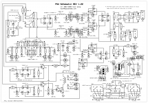
"-Generally speaking is very good practice for OTL tube amps based on 6c33c power tubes to have some LS protection unit , but in case of this OTL amp it is not so necessary , as Tim M. says in his OTL amp article."
DC offset is never indicated visually (least you can do!) only but metering that is fair but allow the speaker to be connected under (high) DC offset is not very clever thing to do IMHO.
DC offset is never indicated visually (least you can do!) only but metering that is fair but allow the speaker to be connected under (high) DC offset is not very clever thing to do IMHO.
By the way, although a catastrophic failure of a 6C33C in which anode shorted to cathode is probably pretty unlikely, there is an almost as catastrophic thing that could actually occur with the Tim Mellow design. Namely, if one of the EF86 driver tubes failed by becoming non-conducting, or if it was simply removed from its socket (or came loose with a bad pin connection), then it could mean that a 6C33C grid would then be connected to its anode via the 100K resistor R12 or R13, with nothing to pull the grid voltage downwards. That would drive the 6C33C heavily into conduction.
On the "con" side, by shorting out R33 it means that if some catastrophic fault condition caused one of the 6C33C tubes to develop, for example, an anode to cathode short, then the full 150V would be applied directly to the speaker cone. One would have to hope that the fuses FS1 or FS2 saved the speaker!
IME if you simply have a fuse in series with the 6C33 then you will have no worries either way. In practice I use 1.5Amp slow blows and they seem to work quite well.
Chris (cnpope)
-Generally speaking is very good practice for OTL tube amps based on 6c33c power tubes to have some LS protection unit , but in case of this OTL amp it is not so necessary , as Tim M. says in his OTL amp article .
- For this type of OTL amps it is just good to have completely separate PSU`s, same as Tyimo want to made ,
with separate PSU`s there will be minimum channel interaction,
special on the DC bias and DC offset points .
- Now in the worst case scenario if one 6c33c power tube arcing or become internally short that R33 ( 1K/10W ) will save LS coil from permanent damage,
- for example if upper tube shorts ,
upper 3,15A slow blow fuse will open immediately , LS coil will be shattered but will be not melted permanently ,
remaining active lower power tube which are biased to conduct normally at around 200-250mA will introduce some unwanted DC power via LS coil ,but greatly limited with 1K value of that R33 and also with Ri of the same power tube ,
in the mid time if DC protection unit is present it will be already activated .
A couple of remarks. If R33 is present, then when you say "upper 3,15A slow blow fuse will open immediately", you must be meaning because of the upper smoothing capacitor, which is charged to 150V, discharging through the loudspeaker (via the fuse FS1)? In other words, my scenario 1 in my previous post? In which case, as I emphasised in my post, the fuse FS1 would equally well have opened immediately in the case when the transformer centre tap is instead connected directly to ground. That is to say, if FS1 blows when R33 is present, it would, a fortiori, blow if instead R33 is replaced by a direct connection of the transformer centre-tap to ground.
I think the only circumstance under which the presence of R33 ostensibly has the chance to alter the fate of FS1 or the speaker coil is in the scenario I called number 3 in my previous message, where neither FS1 nor the speaker coil blows. But then, as I argued, if FS1 and the speaker coil are left intact, it then means, with the semi-floating power supply, that the lower smoothing capacitor will then have the full 300V across it, and also that the lower 6C33C will have 300V cathode-anode voltage instead of the 150V it is supposed to have. This will mean the lower 6C33C will be passing a very large current, and possibly itself also suffering a catastrophic failure, and so the loudspeaker will be facing a second chance to be zapped. I focused on the possible collateral damage to the other channel in a stereo amplifier in my previous post, but the same danger exists even for a single-channel amplifier, as described above. And, into the bargain, the lower capacitor will likely be hugely over-voltaged, and may itself suffer a catastrophe.
So in summary, I really don't see that there is any catastrophic tube failure scenario in which it is likely to be advantageous to have R33 rather than a directly-grounded transformer centre tap, even for a mono amplifier.
I think some sort of crowbar speaker protection, along the lines of ESP in Project 120, might be worth considering. The Velleman loudspeaker protector mentioned by brommermartin looks interesting, but I suspect it might act too slowly in the event of a catastrophic tube failure. It could be good for reacting to a slow tube deterioration or failure, perhaps, in which the DC offset voltage was gradually creeping upwards until it reached the threshold.
Chris
PS: A typical circlotron is, in the respects relevant for this discussion, closely analogous to the situation for the Tim Mellow amplifier where one connects the transformer centre-tap directly to ground, with no R33 resistor. That is to say, one has two closed loops, each comprising an output tube in series with the loudspeaker and a power supply capacitor that is directly driven by a rectified transformer secondary winding. If an output tube developed an anode-to-cathode short, then the only thing that would save the speaker would be the fuse (if installed) in series in that loop. As Ralph (reassuringly!) reports, the fuse does indeed typically save the day.
Last edited:
IME if you simply have a fuse in series with the 6C33 then you will have no worries either way. In practice I use 1.5Amp slow blows and they seem to work quite well.
That is good to hear! I have never experienced a catastrophic failure that would put this to the test, so I have never had the chance to see whether the fuse fails or the loudspeaker coil fails first. I typically use 1.5 amp or 2 amp fuses (separate for each channel), so I am reassured by what you say!
Chris
I've certainly seen them fail- they get your attention! But so far the fuses have prevented troubles with the speaker, except in the cases where the speaker can't handle the power the amp can make (like a PHY or something that can only handle 20 watts or so). In that case you just install a fuse in series with the speaker, or derate the fuses for the power tubes accordingly.
“I think some sort of crowbar speaker protection, along the lines of ESP in Project 120, might be worth considering. The Velleman loudspeaker protector mentioned by brommermartin looks interesting, but I suspect it might act too slowly in the event of a catastrophic tube failure. It could be good for reacting to a slow tube deterioration or failure, perhaps, in which the DC offset voltage was gradually creeping upwards until it reached the threshold.”
1/2 sec is too slow, esp when the DC offset is very high, a pair of zener say 50V back to back shunting the output will limit the DC low enough to be safer. Beside monitoring speaker output terminal is not enough, as it'll turn on again after sometimes, that maybe fatal. IMHO, the HT+- should be monitored as well, and the cut out relay will stay off if any one of rails is out. If the DC is high it could be dangerous, as you pull the speaker the DC is much higher now and according IEC regulation not more 50V should allowed at any one time at the speaker posts. I only have 1A fuse for 25W.
1/2 sec is too slow, esp when the DC offset is very high, a pair of zener say 50V back to back shunting the output will limit the DC low enough to be safer. Beside monitoring speaker output terminal is not enough, as it'll turn on again after sometimes, that maybe fatal. IMHO, the HT+- should be monitored as well, and the cut out relay will stay off if any one of rails is out. If the DC is high it could be dangerous, as you pull the speaker the DC is much higher now and according IEC regulation not more 50V should allowed at any one time at the speaker posts. I only have 1A fuse for 25W.
Attachments
Hi Chris and Banat!
I tried the R33 shorted out and I got HT2:+172VDc and HT4: -171VDc. Looks good!
HT3:-502Vdc without load. Is it O.K. without load??
Next will be to try the 39K/5W bleeder resistors. Can I use a higher value with lower wattage resistors?
Greets:
Tyimo
I tried the R33 shorted out and I got HT2:+172VDc and HT4: -171VDc. Looks good!
HT3:-502Vdc without load. Is it O.K. without load??
Next will be to try the 39K/5W bleeder resistors. Can I use a higher value with lower wattage resistors?
Greets:
Tyimo
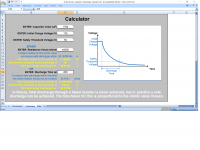
Hi there, there is standard way of calculating bleeder value, it's the safety threshold value you need to remember after calculation, better attach a warning label:" Caution: High voltages, allow X mins after turn off before servicing." Attached is an example of calculation. To ensure highest safety always measure the high voltage supply to ensure it's safe to work on.
Attachments
Hi Koonw!
Thanks a lot!!!
It looks like I don't need to use 5W resistors. That is fine, because I have not enough place on the PCB.
Greets.
Tyimo
Thanks a lot!!!
It looks like I don't need to use 5W resistors. That is fine, because I have not enough place on the PCB.
Greets.
Tyimo
Last edited:
Hi Chris and Banat!
I tried the R33 shorted out and I got HT2:+172VDc and HT4: -171VDc. Looks good!
HT3:-502Vdc without load. Is it O.K. without load??
Next will be to try the 39K/5W bleeder resistors. Can I use a higher value with lower wattage resistors?
Greets:
Tyimo
Tyimo,
You are right, the two raills became equal, but take care not to change Tim's design-floating point PSU. Make some listening tests shorted-unshorted. Also read again Tim's function description. I am confident in Tim's design, nevertheless there are some weak points to be improved.
By the way, noboady speaks about listening test/impressions ....why?
Victor
Hi!
Today I tested the PSU versions:
1. R33 shorted out, no bleeder resistors: I got HT2:+172VDc and HT4: -171VDc. Looks good!
HT3:-502Vdc without load.
2. R33 shorted out and 67K/2W bleeder resistors and 2x230V/50W light bulbs load: I got HT2:+165VDc and HT4: -165VDc. The ballance looks perfect!
HT3:-498Vdc. Is it not too high?
3. R33 is 1K/10W, and 67K/2W bleeder resistors and 2x230V/50W light bulbs load: I got HT2:+14.8VDc and HT4: -19.5VDc!!! Totaly not balanced again!!!
I used this time a 2x12VAC transformer.
quote from the original description about R33:
and so I have the significant imbalance in the supply voltages HT2 and HT4?!?😕 I don't think so....
I think I will leave out the R33, as Chris suggested. It just cause me trouble...There are F1 and F2 to protect.
Greets:
Tyimo
Today I tested the PSU versions:
1. R33 shorted out, no bleeder resistors: I got HT2:+172VDc and HT4: -171VDc. Looks good!
HT3:-502Vdc without load.
2. R33 shorted out and 67K/2W bleeder resistors and 2x230V/50W light bulbs load: I got HT2:+165VDc and HT4: -165VDc. The ballance looks perfect!
HT3:-498Vdc. Is it not too high?
3. R33 is 1K/10W, and 67K/2W bleeder resistors and 2x230V/50W light bulbs load: I got HT2:+14.8VDc and HT4: -19.5VDc!!! Totaly not balanced again!!!
I used this time a 2x12VAC transformer.
quote from the original description about R33:
Is it possible that I have " small offset voltage across the bulbs":If its value
were too small, either an output tube or
the loudspeaker or both could be damaged.
If its value were too high, a small
offset voltage across the loudspeaker
could cause a significant imbalance in
the supplv voltages HT2 and HT4.
and so I have the significant imbalance in the supply voltages HT2 and HT4?!?😕 I don't think so....
I think I will leave out the R33, as Chris suggested. It just cause me trouble...There are F1 and F2 to protect.
Greets:
Tyimo
Last edited:
Hi!
Today I tested the PSU versions:
1. R33 shorted out, no bleeder resistors: I got HT2:+172VDc and HT4: -171VDc. Looks good!
HT3:-502Vdc without load.
2. R33 shorted out and 67K/2W bleeder resistors and 2x230V/50W light bulbs load: I got HT2:+165VDc and HT4: -165VDc. The ballance looks perfect!
HT3:-498Vdc. Is it not too high?
3. R33 is 1K/10W, and 67K/2W bleeder resistors and 2x230V/50W light bulbs load: I got HT2:+14.8VDc and HT4: -19.5VDc!!! Totaly not balanced again!!!
I used this time a 2x12VAC transformer.
quote from the original description about R33:
Is it possible that I have " small offset voltage across the bulbs"
and so I have the significant imbalance in the supply voltages HT2 and HT4?!?😕 I don't think so....
I think I will leave out the R33, as Chris suggested. It just cause me trouble...There are F1 and F2 to protect.
Greets:
Tyimo
Tyimo
You can practice balancing the two raills using the offset adj but only with the tubes inserted. It is verry effectiv.
Regarding the higher values on both HT2 and HT4 you have to start from the transformer. Check the primary volage, then check with no load the sec. You must read some 120Volts.
My advice is to keep in place the R33 as the signal has to pass thru the smoothing caps not thtu the sec, windings.
In order to check the bias supply HT3 you need a 84-89K /5W resistor as the curent shall be 6-5mA and you shall reed -430 V (+/-4) depending on ac mains.
Victor,
My advice is to keep in place the R33 as the signal has to pass thru the smoothing caps not thtu the sec, windings.
Victor,
The audio signal would never really be passing through the secondary windings, regardless of whether R33 is present or shorted out. In fact, for a large fraction of the 60Hz or 50Hz mains cycle, the rectifier diodes are non-conducting, and so the transformer secondary windings are then effectively disconnected altogether. The audio signal always routes through the smoothing capacitors.
I think that, as Ralph reported, the appropriate use of fuses should achieve all that can be done as far as protecting the speaker in case of catastrophic tube failures is concerned. As I remarked previously, if R33 is present then there are some possibly catastrophic follow-on events that could occur in the case that the fuse protecting the loudspeaker did not blow. And if, on the other hand, the fuse did blow, then it would also have blown in the case that R33 is shorted out.
By the way, Ralph's experience with fuses successfully protecting the loudspeaker is in the case of a circlotron amplifier. In all respects relevant to the present discussion, the set-up in the circlotron is directly analogous to the set-up in the Tim Mellow amplifier when R33 is shorted out. That is to say, one has circuit loops comprising an output tube, the loudspeaker, and a smoothing capacitor that is directly driven by a rectified transformer secondary winding. Any objection on safety grounds that is raised to the proposal to operate the Tim Mellow amplifier with R33 shorted out would be equally applicable, mutatis mutandis, to the circlotron too. Ralph's accumulated experience with failure conditions in the circlotron would seem to support the idea that the fuses successfully do their job when the need arises.
Chris
The audio signal would never really be passing through the secondary windings, regardless of whether R33 is present or shorted out. In fact, for a large fraction of the 60Hz or 50Hz mains cycle, the rectifier diodes are non-conducting, and so the transformer secondary windings are then effectively disconnected altogether. The audio signal always routes through the smoothing capacitors.
Chris
You are right, but as I have that project on my banch, watching & listening, I advice all who can, to listen-change-listen-etc.
As I was asking before, did you guys listen to that amp ?
Victor,
Last edited:
You are right, but as I have that project on my banch, watching & listening, I advice all who can, to listen-change-listen-etc.
As I was asking before, did you guys listen to that amp ?
Victor,
Yes, I use mine more or less every day, since I built it a few years ago. It is a great amplifier.
Chris
Yes, I use mine more or less every day, since I built it a few years ago. It is a great amplifier.
Chris
Did you change annything in the PSU ? I separated HT2/HT4 from HT1 and HT3, then I swiched to a fet CCS instad of R7.
Did you change annything in the PSU ? I separated HT2/HT4 from HT1 and HT3, then I swiched to a fet CCS instad of R7.
No, aside from shorting out R33, I made no other significant changes in the PSU. (I did use single 200V smoothing capacitors rather than than connecting four 63V capacitors in series.)
I didn't try any listening comparisons between R33 in place or shorted out, firstly because I can't see any reason to expect any advantageous audible effect from having it there, and secondly because I am just not comfortable with the "floppiness" and unpredictability of the system if R33 is present. Especially, since my amplifier, like Tim Mellow's, is stereo with the two channels running from the same power supply. I prefer the precision of knowing what each supply rail voltage will be, knowing that untoward events in the left channel won't affect what happens in the right channel, and vice versa, and so on.
Chris
Mine are monoblocks. I used also one pair per unit but decupled with some Arcotronics MKP. What kind of smoothing caps you have used ?
Last edited:
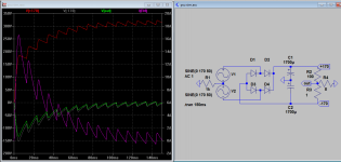
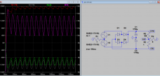
R33 1k sim compared with 1 ohm
This may help to see better the impact for R33 in or out. I think either way the fuse will blow due to some 15A initial discharged into speaker, hence no protection, if fuse does not blow, +170V will be +300V!! which pretty much what you don't want to happen (as already pointed out).
This may help to see better the impact for R33 in or out. I think either way the fuse will blow due to some 15A initial discharged into speaker, hence no protection, if fuse does not blow, +170V will be +300V!! which pretty much what you don't want to happen (as already pointed out).
Attachments
- Home
- Amplifiers
- Tubes / Valves
- New Tim Mellows OTL project