"What kind of smoothing caps you have used ?"
I use 200V/1000u but they do not last very long due to heat (hotter if you player louder) and thus has gassing problem which cause them to budge and then cause more leakage and heat eventually dried up and stop working (opened). The better one would be 315V/1000uf or similar is the next one I want to try, as the higher the voltage the lower is leakage, the longer they will last.
I use 200V/1000u but they do not last very long due to heat (hotter if you player louder) and thus has gassing problem which cause them to budge and then cause more leakage and heat eventually dried up and stop working (opened). The better one would be 315V/1000uf or similar is the next one I want to try, as the higher the voltage the lower is leakage, the longer they will last.
This may help to see better the impact for R33 in or out. I think either way the fuse will blow due to some 15A initial discharged into speaker, hence no protection, if fuse does not blow, +170V will be +300V!! which pretty much what you don't want to happen (as already pointed out).
By the way, my OTL was designed to match with my Quad's ESL 63, so there is an OT between and the quad protection, in case.....
Fortunately it was no need till now.
"What kind of smoothing caps you have used ?"
I use 200V/1000u but they do not last very long due to heat (hotter if you player louder) and thus has gassing problem which cause them to budge and then cause more leakage and heat eventually dried up and stop working (opened). The better one would be 315V/1000uf or similar is the next one I want to try, as the higher the voltage the lower is leakage, the longer they will last.
Right, mine are Philips 1500uF/385V...excelent old stuff
"What kind of smoothing caps you have used ?"
I use 200V/1000u but they do not last very long due to heat (hotter if you player louder) and thus has gassing problem which cause them to budge and then cause more leakage and heat eventually dried up and stop working (opened). The better one would be 315V/1000uf or similar is the next one I want to try, as the higher the voltage the lower is leakage, the longer they will last.
Your Spice simulations are nice; I was planning to run some myself, but you beat me to it!
I can't check which smoothing capacitors I'm using until I get home this evening. I've not noticed any problems with them, but I must admit I haven't monitored them closely for temperature until now. I'll start keeping an eye on them.
Is the heat you mention due to general high temperatures in the enclosure, or is it caused by dissipation due to ripple currents in the capacitors, do you think?
Chris
Not due to temperature, it's touchable I have a cooling fan mounted underside near the caps. It's a Taiwanese made some 10 years ago I heard only 70% Japan's electrolyte I not sure if entirely due to ripple current or gassing due poor electrolyte. But I recently replace a complete set after checking the capacitance they are very close or even over a bit. I also reform the cap once when not in use. This set has little heat I can detect as after 3 months of use now. So..hard to say really, if I know before I sure will go for higher voltage one.
Not due to temperature, it's touchable I have a cooling fan mounted underside near the caps. It's a Taiwanese made some 10 years ago I heard only 70% Japan's electrolyte I not sure if entirely due to ripple current or gassing due poor electrolyte. But I recently replace a complete set after checking the capacitance they are very close or even over a bit. I also reform the cap once when not in use. This set has little heat I can detect as after 3 months of use now. So..hard to say really, if I know before I sure will go for higher voltage one.
Strange, mine are totaly cold, but also the layout is diffrent (caps are down and tubes are up, no need of fan (my oppinion)
Hi Victor!
Thanks! Maybe I will try it later.You can practice balancing the two raills using the offset adj but only with the tubes inserted. It is verry effectiv.
Yes! It is a good idea, thanks!In order to check the bias supply HT3 you need a 84-89K /5W resistor as the curent shall be 6-5mA and you shall reed -430 V (+/-4) depending on ac mains.
[QUOTE I am just not comfortable with the "floppiness" and unpredictability of the system if R33 is present. Especially, since my amplifier, like Tim Mellow's, is stereo with the two channels running from the same power supply. I prefer the precision of knowing what each supply rail voltage will be, knowing that untoward events in the left channel won't affect what happens in the right channel, and vice versa, and so on.[/QUOTE]
I feel the same way!🙂 I prefer the precision of knowing what each supply rail voltage will be.....
Greets:
Tyimo
I feel the same way!🙂 I prefer the precision of knowing what each supply rail voltage will be.....
Greets:
Tyimo
Why not?One more PSU question:
In the heather :R17-18-19-20 are realy 0.5W resistorts?
Each sees 3.15 volts, and they are 47 ohms in the circuit that I have.
P = V^2/R = 3.15 * 3.15 / 47 = 0.211 watts for each resistor.
You could use a higher wattage, maybe 1 watt, but there's little benefit in using anything much bigger than that.
[QUOTE I am just not comfortable with the "floppiness" and unpredictability of the system if R33 is present. Especially, since my amplifier, like Tim Mellow's, is stereo with the two channels running from the same power supply. I prefer the precision of knowing what each supply rail voltage will be, knowing that untoward events in the left channel won't affect what happens in the right channel, and vice versa, and so on.
I feel the same way!🙂 I prefer the precision of knowing what each supply rail voltage will be.....
Greets:
Tyimo[/QUOTE]
OTL amp is a musical instrument, shall be not perfect. You have to enjoy the music it produce.
Why not?
Each sees 3.15 volts, and they are 47 ohms in the circuit that I have.
P = V^2/R = 3.15 * 3.15 / 47 = 0.211 watts for each resistor.
You could use a higher wattage, maybe 1 watt, but there's little benefit in using anything much bigger than that.
Thanks!
Victor!
Could you suggest me how to creat a stand alone -430VDC?
How did you separated HT1 and HT3?Did you change annything in the PSU ? I separated HT2/HT4 from HT1 and HT3, then I swiched to a fet CCS instad of R7.
Could you suggest me how to creat a stand alone -430VDC?
Victor!
How did you separated HT1 and HT3?
Could you suggest me how to creat a stand alone -430VDC?
It's very simple, make another small transformer with adequate sec. (ex. 150V, 350V, and 24V for CCS if you want) 15VA is enought. So you shall clean up PSU and especialy the function of ecc83.
Victor,
Thanks Victor!
It is very nice, but too complex for me.
I am looking for a simple, foolproof design.
It is very nice, but too complex for me.
I am looking for a simple, foolproof design.
Thanks Victor!
It is very nice, but too complex for me.
I am looking for a simple, foolproof design.
Than, follow Tim's design step by step, it is verry relyable indeed.
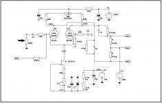
Tyimo, here you are my -430/-15/+146V SUPPLY
FWIW that CCS circuit is leaving a bit of performance on the table. A cascode circuit will work better, resulting in more gain and lower distortion.
FWIW that CCS circuit is leaving a bit of performance on the table. A cascode circuit will work better, resulting in more gain and lower distortion.
You must be right, but unfortunately this is the best I can do for the moment. I am not such skiled to be abble to design a cascode circuit for that purpose....but I am a dam good listener.
After refining what I has started ( maching my OTL with my Quad's 63 switched to 32 ohms ) I shall pass to a CCS based on EF86.
Victor,
Last edited:
FWIW that CCS circuit is leaving a bit of performance on the table. A cascode circuit will work better, resulting in more gain and lower distortion.
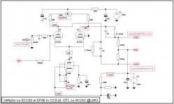
This is what I intend to do next:
Attachments
- Home
- Amplifiers
- Tubes / Valves
- New Tim Mellows OTL project