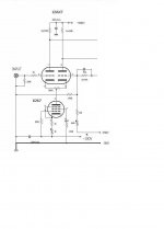
That's better, but if you were to bias the screen with a zener diode and do the same for the control grid, the tube could then reject power supply noise while at the same time providing constant current.
The screen would have the zener to ground, the control grid would have its zener to B-. You could bias both zeners with a common resistor going from control grid to screen grid. With the voltages you have in mind, each zener could be about 40-50 volts and you would have plenty of room to prevent saturation of the tube.
One other thing: **don't** bypass the zeners with a capacitor! That would reduce the effectiveness of the circuit.
That's better, but if you were to bias the screen with a zener diode and do the same for the control grid, the tube could then reject power supply noise while at the same time providing constant current.
The screen would have the zener to ground, the control grid would have its zener to B-. You could bias both zeners with a common resistor going from control grid to screen grid. With the voltages you have in mind, each zener could be about 40-50 volts and you would have plenty of room to prevent saturation of the tube.
One other thing: **don't** bypass the zeners with a capacitor! That would reduce the effectiveness of the circuit.
Thanks a lot, I'll keep in minde all yours advices, hope the final result to be great. I'll keep you informed.
That's better, but if you were to bias the screen with a zener diode and do the same for the control grid, the tube could then reject power supply noise while at the same time providing constant current.
The screen would have the zener to ground, the control grid would have its zener to B-. You could bias both zeners with a common resistor going from control grid to screen grid. With the voltages you have in mind, each zener could be about 40-50 volts and you would have plenty of room to prevent saturation of the tube.
One other thing: **don't** bypass the zeners with a capacitor! That would reduce the effectiveness of the circuit.
This is what inspired me, but is still to work on
Attachments
In a couple weeks i hope the finish my Tim Mellow design OTL 😀
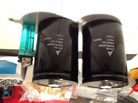
Are these caps usable for the powersupply
Are these caps usable for the powersupply
Attachments
Last edited:
In a couple weeks i hope the finish my Tim Mellow design OTL 😀
Are these caps usable for the powersupply
Verry good choice, nice stuff, must be formatise for best results.
Hi!
I would like to use series caps for C16,17,19 to get over 500V. Do I need to use parallel resistors? What should be the resistance value?
Greets.
Tyimo
I would like to use series caps for C16,17,19 to get over 500V. Do I need to use parallel resistors? What should be the resistance value?
Greets.
Tyimo
Hi!
I would like to use series caps for C16,17,19 to get over 500V. Do I need to use parallel resistors? What should be the resistance value?
Greets.
Tyimo
You can use 100K paralel with each cap for bouth equalise and bleed. And yes 600V shall be better....
Thanks!
Does the C19 to be realy 500V?
Yes C16, 17, 19 - 500V and C18 is 250V but I used al at 550V
One more and hopefuly last question 🙂 :
Is it possible to connect in series the 100uF/500V cap with a 1000uF/63V cap? ( of course parallel each with a 100K/2W resistor.
In capacitance I would get ca. 90uF, but what about the voltage?
I know capacitors connected in series add their voltage tolerances. This is true if their capacitance values are identical.
Last edited:
One more and hopefuly last question 🙂 :
Is it possible to connect in series the 100uF/500V cap with a 1000uF/63V cap? ( of course parallel each with a 100K/2W resistor.
In capacitance I would get ca. 90uF, but what about the voltage?
I know capacitors connected in series add their voltage tolerances. This is true if their capacitance values are identical.
Don't use such discrepant values, if you have 500V caps there is OK you need nothig to add. You shall rich some 450 V after the triplor and 50v of headroom it's ok. Do not complicate such a nice and simple amp.
Be welcome anytime,
Unfortunately, not only confused me more.....
I would be interested, like in one of the question in your suggested site:" What is the maximum voltage that can be applied between the terminals of the series combination of 0.1microF,250V and 0.2microF 500V capacitors?"
The answer was:
So, my question is can it be connected different values caps in series to get higher voltage rating?
I would be interested, like in one of the question in your suggested site:" What is the maximum voltage that can be applied between the terminals of the series combination of 0.1microF,250V and 0.2microF 500V capacitors?"
The answer was:
😕Theoretically, any DC voltage value as the dielectric of the second capacitor will isolate the plates of the first capacitor as they are in series and zero current flows. Then the junction between the two is separated from the source voltage by two insulators. Practically, the DC voltage rating of the lowest value, 250VDC.
So, my question is can it be connected different values caps in series to get higher voltage rating?
All I would like to reach that the PSU could be safe to be tested regardless of any load. With the original values can not do this. The -430Vdc section without load is a bit over 500Vdc! Unfortunately I can not buy 550V ELKO only 400-450-500V.
If you read and understand the article, then you would also understand if the comments beneath it made any sense. Sometimes they don't! Ignore the comments. The article explains how to calculate the voltages on series capacitors if they are the same values or different values.
If the capacitors are the same values, then the resistors in parallel with each capacitor must also be the same values. If the capacitors are different values, then the resistors need to be in the same ratios that you calculate for the values.
Your initial question was for 100uF in series with a 1000uF. As mentioned before, this is not a good plan, because they are too different in value. Ideally they should be the same.
However, in your example if the supply was 550 volts, then...
voltage on 100uF = 550 * (1000 / (100+1000) ) = 500 volts
voltage on 1000uF = 550 * ( 100 / (100+1000) ) = 50 volts
Note that the larger voltage is across the smaller capacitor.
The resistors would need to be in the same ratio as the voltages. In this example across 100uF you would need a resistor 10 times larger than the resistor across the 1000uF capacitor. This is to help maintain the correct voltage balance under all conditions.
I do not wish to discourage you, but really feel that you need to have a better understanding of basic electronics before you start to build this. The questions that you have been asking suggest you do not have the detailed knowledge that you need to build such an amplifier safely, and to be able to find faults and fix them. High voltages in valve circuits can be lethal. Combine high DC voltages with high capacitance and the risks increase significantly. A mistake when building and testing could be the last thing you ever do. No-one here would want to see you or anyone else get hurt.
I know that you want to learn, but there are safer ways to learn, even with valve based electronics. The Tim Mellows design is not the simplest design to build if you have not built with valves or if you do not have a good background in electronics testing or design.
One more and hopefuly last question 🙂 :
Is it possible to connect in series the 100uF/500V cap with a 1000uF/63V cap? ( of course parallel each with a 100K/2W resistor.
In capacitance I would get ca. 90uF, but what about the voltage?
I know capacitors connected in series add their voltage tolerances. This is true if their capacitance values are identical.
Yes, but your voltage balancing resistor is not correct. R1~=50/C=50/100u=0.5M or 470k, and R2=50/1000u=0.05M or 50k. See The Valve Wizard.
Last edited:
Thanks 12E1!If the capacitors are the same values, then the resistors in parallel with each capacitor must also be the same values. If the capacitors are different values, then the resistors need to be in the same ratios that you calculate for the values.
Your initial question was for 100uF in series with a 1000uF. As mentioned before, this is not a good plan, because they are too different in value. Ideally they should be the same.
However, in your example if the supply was 550 volts, then...
voltage on 100uF = 550 * (1000 / (100+1000) ) = 500 volts
voltage on 1000uF = 550 * ( 100 / (100+1000) ) = 50 volts
Note that the larger voltage is across the smaller capacitor.
The resistors would need to be in the same ratio as the voltages. In this example across 100uF you would need a resistor 10 times larger than the resistor across the 1000uF capacitor. This is to help maintain the correct voltage balance under all conditions.

The rest is what you wrote then I will see or better to say hear....😀
Thanks Koonw!Yes, but your voltage balancing resistor is not correct. R1~=50/C=50/100u=0.5M or 470k, and R2=50/1000u=0.05M or 50k. See The Valve Wizard.
Thanks Koonw!
I don't want to discurage, but my advice is too.....take care at hv, can be lethal.
Back to your project, as I told you before, put a 80-90k resistor accross the ht3 and gnd, than you shall not be warry about reaching 500V
- Home
- Amplifiers
- Tubes / Valves
- New Tim Mellows OTL project