Yes, I will do that.Back to your project, as I told you before, put a 80-90k resistor accross the ht3 and gnd, than you shall not be warry about reaching 500V
Greets:
Tyimo
Here are at least 3 areas I can point out and why there are discrepancies.
1) If transformer is 120V then +150/-150 should be +170/-170 as 120*1.42=170. To output +-150 and -430 you need a transformer 150/1.42=105V really.
2) Your own transformer is 125 not 120, the result is near -500V, adjustment sch is attached for reference.
3) C18 should be at least 350V not 250V as specified, and in your case at least 400V.
I hope the clarification will help you and others in future/
Attachments
Last edited:
Thanks Koonw!
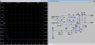
Today I tried my PSU under load: 2x120Vac,260VA transformer, 50W light bulbs on HT2 - HT4 and 85K/5W resistors on HT3. I got:
- 2x 123Vac on the sec.
- 166Vdc HT2-4
- 485 Vdc on HT3!
I think it is still to far from the needed values in the original schematic. So probable I have to adjust it. Thanks for your suggestion and schematic!
Greets:
Tyimo
Usually transformers made with a bit higher voltage than the nominal voltage, so that under load they could give the rated value...., but sure you know it.2) Your own transformer is 125 not 120, the result is near -500V, adjustment sch is attached for reference.
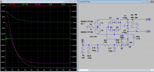
Today I tried my PSU under load: 2x120Vac,260VA transformer, 50W light bulbs on HT2 - HT4 and 85K/5W resistors on HT3. I got:
- 2x 123Vac on the sec.
- 166Vdc HT2-4
- 485 Vdc on HT3!
I think it is still to far from the needed values in the original schematic. So probable I have to adjust it. Thanks for your suggestion and schematic!
All my caps are 500V in the -430 line c16,17,18,19. , but anyway I Thank you for the warning!3) C18 should be at least 350V not 250V as specified, and in your case at least 400V.
Greets:
Tyimo
Thanks Koonw!
Usually transformers made with a bit higher voltage than the nominal voltage, so that under load they could give the rated value...., but sure you know it.
Today I tried my PSU under load: 2x120Vac,260VA transformer, 50W light bulbs on HT2 - HT4 and 85K/5W resistors on HT3. I got:
- 2x 123Vac on the sec.
- 166Vdc HT2-4
- 485 Vdc on HT3!
I think it is still to far from the needed values in the original schematic. So probable I have to adjust it. Thanks for your suggestion and schematic!
All my caps are 500V in the -430 line c16,17,18,19. , but anyway I Thank you for the warning!
Greets:
Tyimo
You definetly need 117-119 V on your sec. If you have thoroid transformer, the only way is to add some winds and put in series with the primary in order to change the ratio primary/sec. It's a practical trick.
In case you have the specs of the trafo is easyer, if not, find out the no of winds/volt...by winding 10 winds and see what you r
This is what inspired me, but is still to work on
A pentode can be an excellent CCS. However, I would get rid of the balancing pot in the cathodes of the differential amplifier! It causes more problems than it solves! If your CCS really works right then the AC balance pot won't be all that useful.
A pentode can be an excellent CCS. However, I would get rid of the balancing pot in the cathodes of the differential amplifier! It causes more problems than it solves! If your CCS really works right then the AC balance pot won't be all that useful.
You must be right about the pot in the cathodes, I shall try this one (attached) with the pot in the anodes, just in case I must adjust the DC offset . If not, I'll live the 100K anode resistors as Tim's original design. Without the ccs, the pot in the cathodes is verry effectiv for the output DC adj as well as +/-150 raills equilibration.
Victor
Attachments
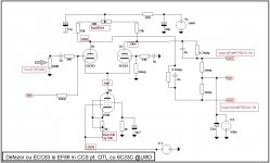
That looks better... I would consider biasing the screen and control grid of the pentode with zener diodes. This will better allow the tube to reject noise from the B- supply. This would require that the cathode resistor be a separate circuit from the control grid.
That looks better... I would consider biasing the screen and control grid of the pentode with zener diodes. This will better allow the tube to reject noise from the B- supply. This would require that the cathode resistor be a separate circuit from the control grid.
Right now I am experementing the 2sk117 CCS , but next, I'll keep in minde your advice for the next step pentode ccs.
Talking about steps to do in my project, the final one shall be 32 ohms load with my ESL 63 modified.
What do you think? see the modified diagram with input trafos in series.
Attachments
Hi,
Its been a while since I did anything to the OTL amp I have just been listening to and enjoying it.
I have done away with the auto transformer and am only using the bench isolating transformer without center tap. I set up the offsets using my dvm and everything remained stable with no problems
...UNTIL...
My son had is 20th birthday party, and I noticed 2 of the 6c33 tubes glowing red! (it was playing very loud at the time but he bias was only at 150ma)
when I checked things out the next day I discovered that someone had tweaked the left hand Chanel offset pot and that the +/-150 volt rails wher 50 volts out i.e. +200 / -100 compared with the signal ground
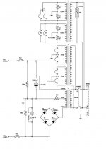
Dave suggested above that a meter would be useful to monitor one of the rails constantly but as my build is complete I have no room for one, what I needed was some sort of zero volts detector that would show me whether the of-sett wad positive or negative
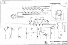
I have searched the web for ideas for an offset detector and found nothing of use so I designed this one from scratch
circuit attached
I have build your voltage offset detector but it is not working properly🙁🙁
The red and orange led are on at the same time 😕
What is wrong...
Right now I am experementing the 2sk117 CCS , but next, I'll keep in minde your advice for the next step pentode ccs.
Talking about steps to do in my project, the final one shall be 32 ohms load with my ESL 63 modified.
What do you think? see the modified diagram with input trafos in series.
The ESL 63 traditionally is a very OTL-friendly loudspeaker. I think this should be an excellent combination!
The ESL 63 traditionally is a very OTL-friendly loudspeaker. I think this should be an excellent combination!
Allready OTL/ESL sounds great as it is (8ohms) but series linkt transformers shall give a near clas A behaviour of my OTL's
I hope trafos behaviour in series shall not rise other maching or balancing problems......Only one man should know ...but is gone, P. Walker indeed.
Hi Tim's OTL diy-er
There is at least one of you to have "play" with diffrent quality/value caps in the signal path (C1,2 & C3,4) ?
If yes, what opinion do you have, what did you experienced?
I think it matters.
Victor
There is at least one of you to have "play" with diffrent quality/value caps in the signal path (C1,2 & C3,4) ?
If yes, what opinion do you have, what did you experienced?
I think it matters.
Victor
Last edited:
"My conclusion is that the simplest of power supplies, provided that the capacitors are reasonably big (4,400uF in my Tim Mellow amp), is more than adequate. Hum is simply not an issue." Chris, as you can see, I have popped over to this thread. I'm slowly working my way through it. It's very informative about the Mellow OTL. Can I ask you if you mean 4,400uF in total or 4,400uF each half.
I am planning my projects for the summer and this amp is next up. However, I want to use 2 3b28 half wave rectifier tube. How would I wire them?
"My conclusion is that the simplest of power supplies, provided that the capacitors are reasonably big (4,400uF in my Tim Mellow amp), is more than adequate. Hum is simply not an issue." Chris, as you can see, I have popped over to this thread. I'm slowly working my way through it. It's very informative about the Mellow OTL. Can I ask you if you mean 4,400uF in total or 4,400uF each half.
I'm using 4,400uF for each half. Two 2,200uF capacitors in parallel for each half.
Chris
"My conclusion is that the simplest of power supplies, provided that the capacitors are reasonably big (4,400uF in my Tim Mellow amp), is more than adequate. Hum is simply not an issue." Chris, as you can see, I have popped over to this thread. I'm slowly working my way through it. It's very informative about the Mellow OTL. Can I ask you if you mean 4,400uF in total or 4,400uF each half.
I use 1500uF each half on my monoblocks, but they are Philips 350V with 12A/20khz
This is more than enought if you insert also some 10-15 uF MKP
I think more important is separating the 4 PSU not to interact and also provide decent rectifiers with high peak current (100A or more)
"My conclusion is that the simplest of power supplies, provided that the capacitors are reasonably big (4,400uF in my Tim Mellow amp), is more than adequate. Hum is simply not an issue." Chris, as you can see, I have popped over to this thread. I'm slowly working my way through it. It's very informative about the Mellow OTL. Can I ask you if you mean 4,400uF in total or 4,400uF each half.
I'd go with the largest values you can- at higher power levels, the extra bypass amounts to lower IM which is heard easily enough.
We use a total of 12,000 uf in the supplies of our 60-wat amps- that seems to be at the point on the curve of vastly diminishing returns.
I'm a builder with very little understanding of electronics so bare with me. I have 4 big blue 2200uf caps in my stash. What parts of the schematic to I use these in as a substitute?
I'm a builder with very little understanding of electronics so bare with me. I have 4 big blue 2200uf caps in my stash. What parts of the schematic to I use these in as a substitute?
What voltige are yours cops ? It must be at least 200V but my advice is 250-350V . They shall substitute the 4x6800uF of each raill in Tim's PSU schematic.
Attachments
Last edited:
- Home
- Amplifiers
- Tubes / Valves
- New Tim Mellows OTL project