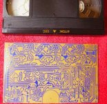
Those who've scrutinised my PC-board layout very closely, will see that I've changed the design slightly from the circuit which I posted a while back. Now LM317T and LM337T ICs on both supplies:
(i) the are better performing chips than the 78- and 79- fixed regulators.
(ii) I'm still not exactly certain what voltages I want. With the 317/337 chips the voltage can be set anywhere just by specifying 1 or 2 resistors, rather than swapping the IC itself.
(i) the are better performing chips than the 78- and 79- fixed regulators.
(ii) I'm still not exactly certain what voltages I want. With the 317/337 chips the voltage can be set anywhere just by specifying 1 or 2 resistors, rather than swapping the IC itself.
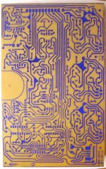
I'm getting close to finishing up the printed circuit layout for the board which will contain these circuit blocks:
As always, when the board gets close to finished, squeezing in the last few components and tracks becomes annoyingly tricky. A few more days ought to suffice. I hope!
- the 3-phase power stage,
- the exciter oscillator,
- the 3-phase AM phase detector,
- the tacho preamp & wave shaper.
As always, when the board gets close to finished, squeezing in the last few components and tracks becomes annoyingly tricky. A few more days ought to suffice. I hope!
I have updated the power supply web schematic / circuit-diagram to match the one I used for the PCB layout. This is its 'final' form, unless things go unexpectedly later on.
sp10psu.gif
sp10psu.gif
Here is now the entire drive circuit (schematic), excluding the PLL section, which will plug into the socket on the bottom left of the diagram:
drivepc.gif
This is the schematic that matches the printed circuit board artwork (except the component reference don't match up yet)
poa.gif
With this board, the motor will be able to be run - although not with quartz accuracy.
drivepc.gif
This is the schematic that matches the printed circuit board artwork (except the component reference don't match up yet)
poa.gif
With this board, the motor will be able to be run - although not with quartz accuracy.
In a private message I was asked:
I think I used those letters to stand for "Negative Feedback / Zero Balance".
It is the feedback signal derived from the motor's star-point, filtered and buffered.
If there is any asymmetry in the motor armature windings (due to physical tolerances of construction) this signal compensates for that by adjusting the drive so the star point is always at zero volts. In a perfect motor the star point would always be at zero volts and need no external connection.
With star-point feedback, the torque is more uniform within a single rotation. It's not strictly necessary, but it takes some of the burden off the servo system to have as linear-as-possible motor.
but what does signal name "NFZB" stand for and who generates this signal?
I think I used those letters to stand for "Negative Feedback / Zero Balance".
It is the feedback signal derived from the motor's star-point, filtered and buffered.
If there is any asymmetry in the motor armature windings (due to physical tolerances of construction) this signal compensates for that by adjusting the drive so the star point is always at zero volts. In a perfect motor the star point would always be at zero volts and need no external connection.
With star-point feedback, the torque is more uniform within a single rotation. It's not strictly necessary, but it takes some of the burden off the servo system to have as linear-as-possible motor.
Thanks for the explanation.
So, how does one adjust the NFZB signal? I see the potentiometer for the adjustment in your schematic but am unclear on how I'd go about setting it.
Sorry to be so dense but am I to adjust until "NFZB" and "Star" are at equal potential (voltage)?
Since one leg of the pot is connected to ground, it's pointless to adjust to 0V in reference to ground.
p.s. The schematic names the signal as "NZFB". I assume this is a transposed typo.
So, how does one adjust the NFZB signal? I see the potentiometer for the adjustment in your schematic but am unclear on how I'd go about setting it.
Sorry to be so dense but am I to adjust until "NFZB" and "Star" are at equal potential (voltage)?
Since one leg of the pot is connected to ground, it's pointless to adjust to 0V in reference to ground.
THEORETICALLY - since I have not finished building it yet:
The pot would be adjusted by putting an oscilloscope on the motor's star point, (referenced to power supply ground, 0V) and adjusting for minimum (or zero hopefully) amplitude. A centre-zero moving coil meter would also work.
The NFZB signal will be an asymmetrical sum of 3 sinewaves. By addng more feedback, they ought to be supressed. I have no idea what the variation among the production run of motors was, hence the adjustment rather than just puttting in values based on my particular motor.
p.s. The schematic names the signal as "NZFB". I assume this is a transposed typo.
Probably done late at night! I can't exactly remember what I invented the acronym to stand for. Maybe it was Negative Zero-point Feedback. It's all the same signal though. That actually sounds better than my previous guess 🙂


This is getting closer and closer to realization of both custom/modernized power supply AND controller...
I read every day with anxious hope...
Rick
I read every day with anxious hope...
Rick
I read every day with anxious hope...
This is good to hear! It helps me avoid getting sidetracked on other projects when I know people are waiting to see how things progress.
I am also reading every post in anticipation of the final product.This is good to hear! It helps me avoid getting sidetracked on other projects when I know people are waiting to see how things progress.
I am also reading every post in anticipation of the final product.
This is good to hear! It helps me avoid getting sidetracked on other projects when I know people are waiting to see how things progress.
And you can add ME to this list!! Deepest gratitude as well!
I've been chopping & hacking at pieces of aluminium extrusion to make the heatsink. Since it (heatsink) is an integral part of the PC board's mounting setup, I need to be sure it all fits in neatly (not an enormous amount of free space there) before I actually etch the board.
Add me to the list of very enthusiastic followers of this post 🙂 I have one of the ex-BBC SP-10 Mk2s with dodgy electronics, so I'd love to get that working not just properly but better than ever.
Cheers, Jon.
Cheers, Jon.
My heatsink and aluminium flange hackings have paid off:
An externally hosted image should be here but it was not working when we last tested it.
- Home
- Source & Line
- Analogue Source
- New Technics SP10 motor controller specification