My mech. brake was removed as part of a big tweeking-out. How much that contributes to the much lower than BBC guise noise floor I simply don't know. But we could see no use for it in normal usage.
It also just occurred to me that the platter does not need to stop dead, but could spin down to an assisted stop. I wonder, though, if a set of coils could be energised so that the platter is held in position when it stops...?
It also just occurred to me that the platter does not need to stop dead, but could spin down to an assisted stop. I wonder, though, if a set of coils could be energised so that the platter is held in position when it stops...?
I am getting older, but am fortunate to have very steady hands and also exceptionally fast reflexes - by any standard. For me I find that the platter when freewheeling can be stopped smoothly and safely with the finger tips (naturally only once the arm has been parked.). I can't see any reason for a brake of any type. I am now using an old cleaned up Lenco in a slate plinth with a Zeta arm.....IF you want a budget set-up this is the way to go. Very cool TT. Despite this performing way above any reasonable hopes, I have a slate block ready for final machining for Kenata usage for my SP 10. I am looking forward very much to the new PS becoming available!!
Looking back over the last page or two, I see that I promised to post pics of my off-board PS in the rackmount chassis which comes with the SP10-P. I'll try and get this on the forum this week!!!
I've been re-doing the PCB layout according to the 'size' contraints of the real chassis, & hopefully will have a finished piece of artwork by early next week.
"Electronic braking" I like, it's sort of sexy, and I like a stationary platter when I get to it to turn the record over. Keeping the armature partially energized with a static field would 'hold' the platter and prevent it from turning; what would one need this sort of feature for? It does make the drive electronics more complex, and I hadn't really planned on doing that.
There are two possible schemes of "electronic braking":
(i) setting the drive amplifier's output to zero volts (not just switching off the amplifiers) is similar to putting a short circuit across the motor and will damp freewheeling rotation quite fast. This is an easy experiment - just short circuit all 3 windings (blue, yellow, red and green wires on the motor) together and try to turn the rotor.
(ii) appling reverse torque momentarily will stop the platter *instantly*, but needs careful predictive control to prevent reverse rotation. At very low speeds, the tacho signal ceases to exist, so there is no easy way to monitor speed right down to stand-still.
I'm ultimately going for (ii). Someone wanted a reverse playback option, so bidirectionality is now part of the drive system's capabilities.
And you could add an external (push-)switch for energizing the mechanical brake-solenoid...
Arne K
Arne K
I've been re-doing the PCB layout according to the 'size' contraints of the real chassis, & hopefully will have a finished piece of artwork by early next week.
"Electronic braking" I like, it's sort of sexy, and I like a stationary platter when I get to it to turn the record over. Keeping the armature partially energized with a static field would 'hold' the platter and prevent it from turning; what would one need this sort of feature for? It does make the drive electronics more complex, and I hadn't really planned on doing that.
There are two possible schemes of "electronic braking":
(i) setting the drive amplifier's output to zero volts (not just switching off the amplifiers) is similar to putting a short circuit across the motor and will damp freewheeling rotation quite fast. This is an easy experiment - just short circuit all 3 windings (blue, yellow, red and green wires on the motor) together and try to turn the rotor.
(ii) appling reverse torque momentarily will stop the platter *instantly*, but needs careful predictive control to prevent reverse rotation. At very low speeds, the tacho signal ceases to exist, so there is no easy way to monitor speed right down to stand-still.
I'm ultimately going for (ii). Someone wanted a reverse playback option, so bidirectionality is now part of the drive system's capabilities.
I cannot help but feel that the far greatest number of end users will use this TT as a truly superb simple TT. Options such as reverse rotation, broadcast brakes etc. are simply redundant for those who just play records at home. Serious broadcast people and disco DJs will be in the minority as far as this TT is concerned...there are better tools out there for such purposes.
I am fully aware that we owe a huge debt of gratitude to Steerpike for devoting so much time and mental energy in designing a drive system for this motor. But I for one would be grateful if the design could be simply for a two speed option with absolutely no whistles and bells. Once the power to the motor is switched off the platter can be braked with the finger-tips. Solenoids, relays and other non-essential devices can only degrade the potential purity of the current. AND they are something extra to go wrong. I believe in the KISS principle and feel that for those who want to extract the utmost information from their records that this is the way to go. This TT treated sensibly with regard to plinth construction and with a very good arm/cartridge is capable of critical sound comparison with the very best TTs that can be bought at any price.
However if this is different to the general consensus of requirement I shall be grateful if such addional features are designed in such a way that they can be totally by-passed/hard-wired out at building stage.
Many thanks.
Last edited:
This is certainly true. However, I like the idea of putting all kinds of exotic possibilities into the theoretical design. It's easy to leave a section out when building it, but rather unsatifactory to have to add on bits like piggyback boards, and cutting pcb tracks etc.I cannot help but feel that the far greatest number of end users will use this TT as a truly superb simple TT.
I shall be grateful if such addional features are designed in such a way that they can be totally by-passed/hard-wired out at building stage.
Thats exactly my plan.
Things like the mechanical brake belt: if you want it, there should be some electronics to operate it. If you dont want it, leave out the transistors etc. that energise it.
This is certainly true. However, I like the idea of putting all kinds of exotic possibilities into the theoretical design. It's easy to leave a section out when building it, but rather unsatifactory to have to add on bits like piggyback boards, and cutting pcb tracks etc.
Thats exactly my plan.
Things like the mechanical brake belt: if you want it, there should be some electronics to operate it. If you dont want it, leave out the transistors etc. that energise it.
Thanks...just what I want to hear. Do you have any ideas on an approx. date by which you will be testing a first version?
Do you have any ideas on an approx. date by which you will be testing a first version?
Things keep happening that get in the way of fun; but I'm hoping to have "basic rotation" within a week.
I, too, am interested in the design that keeps it simple (and adds the least amount of electronic / mechanical noise).
That being said, there are a few aspects of your design that I'm really looking forward to (over the stock controller). i.e. If there's anyway to rate them as high priorities, these are what I'd vote for:
1) The ability to sense the platter weight (MOI?) and alter the damping/speed adjusting appropriately. I'd like to play around with different after-market mats and would like to know that the added weight isn't going to alter the speed performance.
2) The ability to finely adjust the speed. As an example and as many have pointed out, 45s are not cut exactly the same all around the world.
I'm less interested in the other design details. I plan to remove the mechanical brake and would like to investigate mounting the motor without the bath tub around it. As a result, I'd like to put as much of the electronics in an outboard chassis.
Chris
p.s. It's great news that a design is so quickly coming. If you don't me asking, what do you plan to come out with and what will be left to the design?
If you don't me asking, what do you plan to come out with and what will be left to the design?
What I need first is a working motor, from which I can take some accurate measurements of its mechanical behaviour. So the first result will be a system that just runs at a speed set by a rotary potentiometer, with no PLL control or reference. (much like several DC belt drive designs)
After that is proved to work, I'll have numbers that I can plug into the PLL servo theory. *IF* the ASM PLL works, then the next step will be quite quick.
I'm hoping to have a basic design that can run minimalistically without a microprocessor. But the micro will add a slicker user interface, and functionality such as numeric speed readout, fine pitch control, auto calibration, etc.
***********
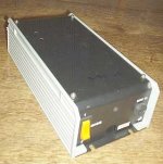
Long ago someone gave me this damaged 'generic' power supply (photos below). It's too complex to waste time reverse engineering it for repair. The transformer is still good, so it will make a neat box for the SP10 power supply, with a new PCB. It's 9" x 4".
The umbilicus between the PSU and the SP10 I'm thinking of terminating with 25pin "D" connectors (as used, though not so much recently, on desktop PC ports These plugs and sockets are inexpensive, easy to source, have lots of pins, and quite good current rating.
Attachments

Its coming along nicely: slowly, but nicely.
A few important criteria for my layout, with a view to keeping it aimed at DIY and lowest possible cost:
single sided board; wide tracks and minimal tracks-between-IC-pads for easy etching, wide component spacing to allow substitute components of varying size, no surace-mount components.
This is a protoype board, so it contains component positions for all possible theoretical circuit arrangements. For instance, the op-amps can be configured as inverting, or non-inverting, by adding specific resistors and omitting others; filters can be 1st order, or 2nd order, depending on resistors & caps added, and so on.
If the board works OK, I will NOT redo the major layout to minimise size, or hole-count / component-position-count. Minor fixups, yes, but the board will remain like this so future experimentation and modifications can be tried.
This all sounds excellent to me. My plan was always to mount it external to the motor unit and a have a spare 19" rack case for it somewhere.Its coming along nicely: slowly, but nicely.
A few important criteria for my layout, with a view to keeping it aimed at DIY and lowest possible cost:
single sided board; wide tracks and minimal tracks-between-IC-pads for easy etching, wide component spacing to allow substitute components of varying size, no surace-mount components.
This is a protoype board, so it contains component positions for all possible theoretical circuit arrangements. For instance, the op-amps can be configured as inverting, or non-inverting, by adding specific resistors and omitting others; filters can be 1st order, or 2nd order, depending on resistors & caps added, and so on.
If the board works OK, I will NOT redo the major layout to minimise size, or hole-count / component-position-count. Minor fixups, yes, but the board will remain like this so future experimentation and modifications can be tried.
I will be speaking to someone next w/e regarding some CNC cutting of ply to make the plinth for mine, as well as for my 401, similar to Albert Porter's plinth.
Been "away" for awhile... my home is "gutted" doing a complete remodel..replacing wiring, plumbing, sheetrock, flooring..and even changing room layouts.
Things are really looking good and looks like Steerpike has been quite busy...which is very very much appreciated!
Again, thanks for the effort! I will keep watching as this progresses...
Great Job!!!
Rick
Things are really looking good and looks like Steerpike has been quite busy...which is very very much appreciated!
Again, thanks for the effort! I will keep watching as this progresses...
Great Job!!!
Rick
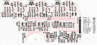
I took a break from the controller and did the copper layout for the power supply board here: psu pcb.
This is 8.1" x 3.9" to fit exactly into the box I showed a few posts back. No doubt your favourite component supplier will have all manner of instrument housings in all kinds of styles, if you choose to use the board layout exatly as I have shown it. (it may have a few mistakes in it still, so don't copy & etch it just yet!)
The five TO-220-package regulators are all in a row - these are to be bolted onto an L-shaped aluminium flange to act as a heatsink.
Note that this power supply is NOT a drop-in replacement for the original SP10 with its factory electronics. It doesn't have the appropriate grounding system - although it could be modified to be compatible with the original.
Last edited:
Nice layout!
That's a very clean layout! If you don't mind me asking, what layout software are you using ?
I've been playing around with a couple of the free-bies (Eagle and 4pcb) and have had to do a huge amount of hand routing due to the difficulties of doing single layer boards with those tools.
I took a break from the controller and did the copper layout for the power supply board here: psu pcb.
That's a very clean layout! If you don't mind me asking, what layout software are you using ?
I've been playing around with a couple of the free-bies (Eagle and 4pcb) and have had to do a huge amount of hand routing due to the difficulties of doing single layer boards with those tools.
That's a very clean layout! If you don't mind me asking, what layout software are you using ?
Tango PCB. By software fashion trends, it's ancient. But nothing newer (in the affordable categories) has impressed me at all.
I'll modify that board a little (a mark 2 version) that doesn't include the transformer on the PC-board, for people who want to use a more generic transformer and housing. Basically, that would amount to chopping off the left-hand half of the board.
I'll modify that board a little (a mark 2 version) that doesn't include the transformer on the PC-board, for people who want to use a more generic transformer and housing.
Like a prophecy coming true....CLICK!
- Home
- Source & Line
- Analogue Source
- New Technics SP10 motor controller specification