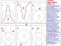
I just realized that i reversed #4 and #6 in the multi-aperture sketch .... Oh well, no biggie, you guys get the idea 🙂
update
Ok , it is all fixed up now 🙂
Ok , it is all fixed up now 🙂
Attachments
Last edited:
dunno if my rough sketch of an aperture would be better or not - hopefully you can try a couple of different openings to observe pros and cons.
You might try the double-ended combined with a circular fire-in-the-middle aperture centered on the driver centerline. This will give deeper bass and great cone control. I have built this and it pulls tuning about 10Hz lower than with the vents and no exit aperture plate.
You might try the double-ended combined with a circular fire-in-the-middle aperture centered on the driver centerline. This will give deeper bass and great cone control. I have built this and it pulls tuning about 10Hz lower than with the vents and no exit aperture plate.
XRK ,
If it were anyone else saying something like that i would think they were just joshing me with satire, but i know that since you do all of that work with foamcore it certainly is easy and convenient enough for you to try plenty of experimental apertures...😉
Chris' 15P1200ND-N
Chris 661 ,
I am checking out your Beyma 15P1200ND-N in the 90 L Karlflex right now ..... With your driver's very low VAS figure and strong motor system it looks a bit underdamped (peak at 35hz with a dip centered around 55hz) in the 90 liter Karlflex as if the driver wants a smaller box or an adjusted design to play flat and reach it's potential .... There are a few ways i could try modifying the model to make it more optimized for your driver and it would likely involve increasing the vent area and using the series tuned K-Aperture (option #1 in the recent aperture sketch) , just let us know if you want me to give it a go ..
P.s.
That driver would also be a great candidate for a Tapped Horn (considerably larger box though) , FLH (even larger than the TH !) or possibly even a DCR (relatively small box ,only a little bigger than a reflex) ... Could even get fancy and try to craft up some sort of new fangled 6th order DCR hybrid sort of beast , depends on how much spare time and access to power tools you have at your disposal 😉
Last edited:
Hi MMJ,
I'm currently doing a Physics degree, so there's not a whole lot of spare time or money.
I've been thinking about doing some really small ported boxes for these drivers, kinda like this: Q15 Compact 15" Bass bin - Speakerplans.com Forums - Page 1
Except I'd just cheat and use the pre-fab 15" car sub boxes and add my own ports and handles.
Some THs would be lovely, but I have no car at the moment, so they'd be nigh-impossible to move anywhere - taxi drivers hate me enough as it is 😉
I'm hoping that the design discussed here will strike a balance between the teeny-tiny ported box that'll chuff at high power, and the big THs which would dismantle small venues.
Chris
Hi MMJ and chris661,
I agree, the Beyma 15P1200Nd/N would work in a TH, but it also works very nicely in the KARLFLEX T-TQWT.
If you take the drawing from Post #1040, and multiply the width by 1.21 you get an external width of 16.335", which is just enough to fit the driver if you use 15/32" plywood. The external volume now is 122L/4.3ft^3.
By the way, the aperture will have to be determined experimentally, but, I like the one in the drawing. That or a similarly placed Keystone. I just don't have the time right now to work out an AkAbak simulation for that one.
I'll attach the Hornresp export file.
(Done on the run. No Warranties. 🙂 )
Regards,
Attachments
I concur! =D
Hey there🙂
Yep , Tb46 is right , a custom width Karlflex works well for your driver Chris ... In that scenario i would open up the "C" (S3/S4) area some, probably to about 3" (instead of 2.5") , allows for better airflow with that high powered driver and also gives a higher FB which will be closer to your target of 35hz in a series tuned (Aperture option #1) Karlflex ....
Also as TB recommended previously you can double the thickness of the baffle and countersink the driver's frame so that it doesn't stick out so much reducing any risk of problems with airflow through that area (could be a critical factor when using this design in it's series-tuned configuration) ... .
Stuffing , in the S1/S2 region (as depicted in sketches) will really help to knock down that peak at FB , and will also spread out the peak in air-particle velocity , reducing the likelihood of chuffing at around FB ........ Even the 90L (19" wide) Karflex works with your driver if you use enough S1/S2 stuffing to knock out the peak , it is just a little larger than you really need, and since you shlep boxes around via taxi smaller is better🙂
Chris , are you planning on using these boxes as just subs or do they need to have more bandwidth to meet up with your EV compression drivers?
These would be as subs. I have 2 pairs of the Beyma drivers, one pair is in some old EV Deltamax cabinets for a 15" two-way setup. The 2nd pair of drivers would be used as subs. More headroom is always nice when it comes to PA/party applications.
The subs will be driven by a PV2600, for around 800w/ch into the 5ohm impedance dips on these drivers.
I have previously run that amp bridged into a pair of those drivers paralleled, but later realised the amp was seeing a bridged 2.5ohm (minimum) load, which is more than a little abusive when you're nudging the clip lights. To say it ran warm is an understatement...
Anyway, I digress.
The subs will be driven out of a DCX2496, so there's plenty of room for steep XOs, notches, etc. it might be worth EQing the low-frequency peak that you allude to, since that'd gain some headroom, rather than absorbing the extra acoustic power.
It'd be easy enough to try both ways, though.
I'm not at home at the moment to simulate this, but will be able to tomorrow.
Cheers
Chris
These would be as subs. I have 2 pairs of the Beyma drivers, one pair is in some old EV Deltamax cabinets for a 15" two-way setup. The 2nd pair of drivers would be used as subs. More headroom is always nice when it comes to PA/party applications.
The subs will be driven by a PV2600, for around 800w/ch into the 5ohm impedance dips on these drivers.
I have previously run that amp bridged into a pair of those drivers paralleled, but later realised the amp was seeing a bridged 2.5ohm (minimum) load, which is more than a little abusive when you're nudging the clip lights. To say it ran warm is an understatement...
Anyway, I digress.
The subs will be driven out of a DCX2496, so there's plenty of room for steep XOs, notches, etc. it might be worth EQing the low-frequency peak that you allude to, since that'd gain some headroom, rather than absorbing the extra acoustic power.
It'd be easy enough to try both ways, though.
I'm not at home at the moment to simulate this, but will be able to tomorrow.
Cheers
Chris
Your PV2600 should be perfect for driving those boxes and since you are using them for subs it should be easy to get them working the way you want without having to worry about extreme upper end response 🙂
You can adjust FB easily enough by changing just how open the aperture is to get things dialed in
 ..
..The stuffing solution is an interesting method because it tends to lower the Q of any peaks (excursion, impedance, response peaks, air particle velocity etc) spreading the resonance around a little resulting in tamed humps where there were once peaks ... Stuffing can also make a box sound more musical and natural ...

The 2nd pair of drivers would be used as subs. More headroom is always nice when it comes to PA/party applications.
Indeed! A single ~180 L [net] TH @ 800 W is all you need for live reproduction of a drum kit, so two will just loaf along unless you have a really large space to fill.
GM
Attachments
hey GM - so for today's drum tunings a 40Hz LF corner should cover the "sub" (?) where can one find truly stellar recordings of jazz drums, hyper speed double kick metal, etc.? Maybe a reasonable size Karlflex would do nice for a reasonably portable electronic drumkit bottom (- you can tell I'm old and come from a pre-dominant PA era when each instrument pretty much stood alone on the stage) what inexpensive but loud drivers could one use with a passive crossover on top for the critical midrange? (MMJ has those bargain CV.)
Last edited:
Hey Freddy!
I haven't followed recordings since 2000 when I was forced to sell off most of my audio gear, etc.. At that time, the best drum vinyl recordings I had were early Pink Floyd, Rick Wakeman, Art Blakey, a ~uncompressed RTR tape of some of Brubeck's finest, ditto a live recording of a Ramsey Lewis show here in '66? by the local Altec distributor/installer to use for demos touting the lack of need to limit compression beyond what the recording medium demanded. These two were cone/dome system killers if the amp was powerful enough to track them.
Not 'sub' except for the parties I know about same as you when a single A7 and 30 pp tube watts was all the sound system a local band needed, but others have posted that a DJ these days may need down to around 25 Hz at ear bleed SPLs for all those weird name music genres today's youths party to.
Don't keep up with all the drivers available today either, you're much more current than me. For the mids, I'd want at least a 12" though.
GM
MMJ, I had a sneaking suspicion I was getting too greedy with those Alpines =(
Regarding the particle velocity, would increasing the narrow path area by 0.5-1" worth of width at the expense of path length while using an aperture that maximized path length (lowest possible bottom exit) be helpful enough!? To be fair, my GX5 can only put out 700-800 watts with a 4Ω load so we can use that as a limit!
Sent from my iPhone using Tapatalk
C&P,
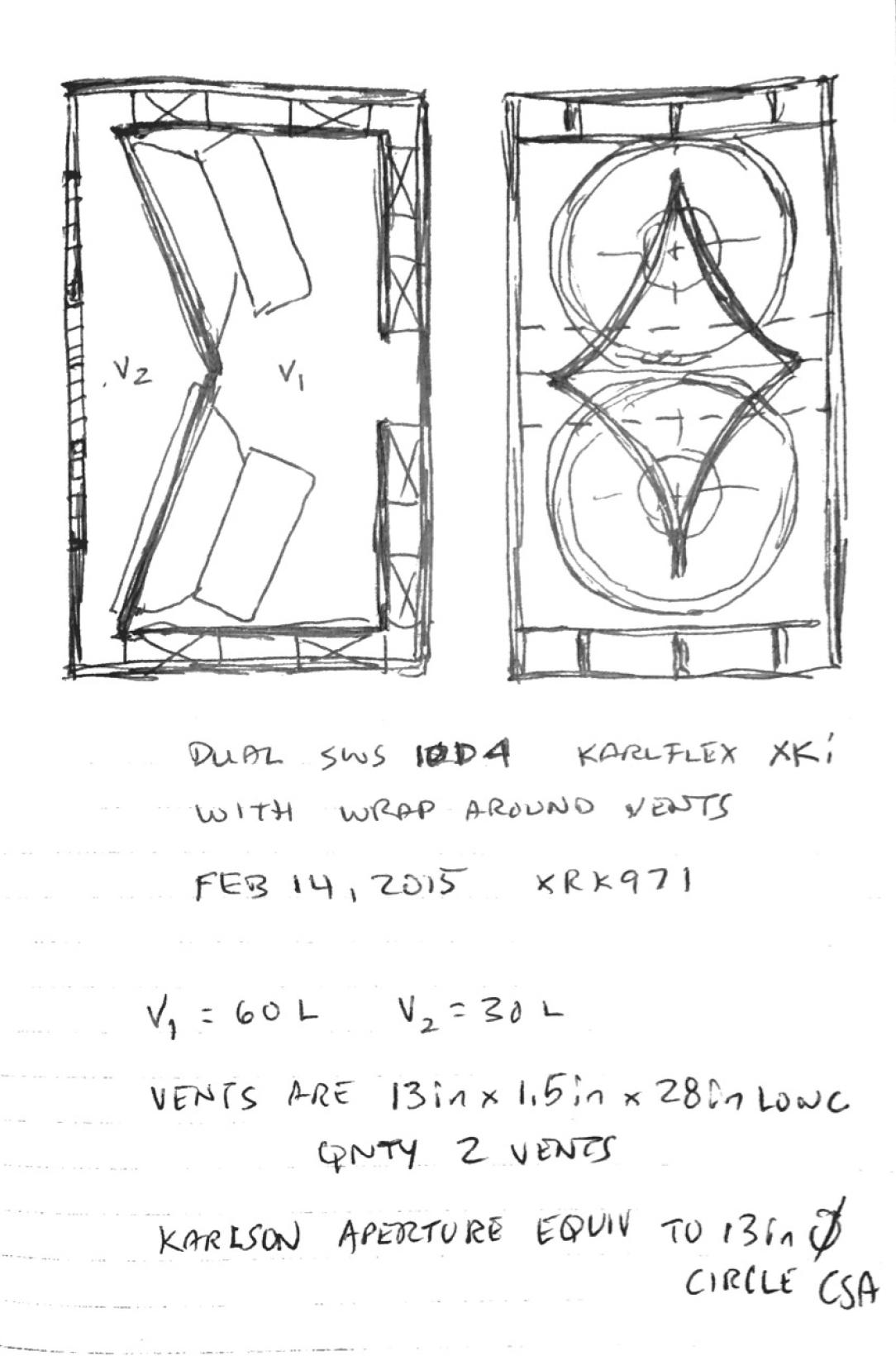
I managed to dig out my ancient laptop that has Akabak on it. So I managed to sim your case of using two SWS-10D4 drivers in a 100 liter or smaller box with 35Hz (f3) and maximal SPL output.
The design I came up with is similar to an XKi but with dual vents to reduce air particle velocity near resonance. Make the box 13in wide internally and make the rear chamber 60 liters and the front 30 liters. The vents are 13in wide x 1.5in tall x 28in long (qnty 2 vents). The drivers are angled a bit to prevent parallel-parallel interference. The output aperture is equivalent to a 13in diam round hole.
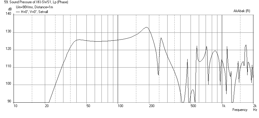
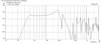
Here is the predicted max SPL at 12mm displacement (I did not want to go to actual xmax levels to keep it linear and to have head room) at 90v RMS. It is a 125dB design with -3dB point at 35Hz:
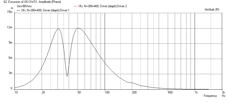
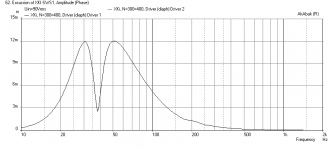
Here is predicted cone displacement with a 30Hz -24dB/oct BW high pass filter to avoid over excursion:
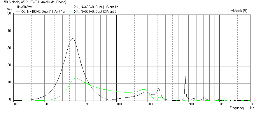
Here is the particle velocity in the vents and output aperture - it hits 30m/s in the vents but this is shaded behind the Karlson aperture so I don't think it is a problem:
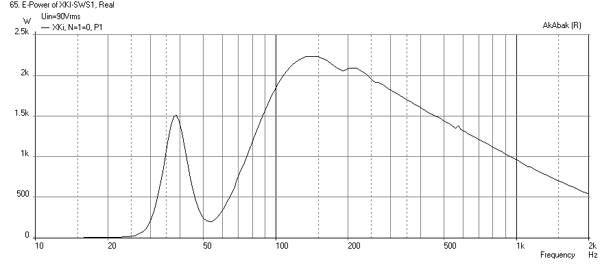
Here is the electrical power input - about 1.5kW:
Here is the code:
I managed to dig out my ancient laptop that has Akabak on it. So I managed to sim your case of using two SWS-10D4 drivers in a 100 liter or smaller box with 35Hz (f3) and maximal SPL output.
The design I came up with is similar to an XKi but with dual vents to reduce air particle velocity near resonance. Make the box 13in wide internally and make the rear chamber 60 liters and the front 30 liters. The vents are 13in wide x 1.5in tall x 28in long (qnty 2 vents). The drivers are angled a bit to prevent parallel-parallel interference. The output aperture is equivalent to a 13in diam round hole.
Here is the predicted max SPL at 12mm displacement (I did not want to go to actual xmax levels to keep it linear and to have head room) at 90v RMS. It is a 125dB design with -3dB point at 35Hz:
Here is predicted cone displacement with a 30Hz -24dB/oct BW high pass filter to avoid over excursion:
Here is the particle velocity in the vents and output aperture - it hits 30m/s in the vents but this is shaded behind the Karlson aperture so I don't think it is a problem:
Here is the electrical power input - about 1.5kW:
Here is the code:
Code:
| 6th order band pass sub for dual Alpine SWS 10D4
| xrk971, Feb 13, 2015

System 'XKi'

Def_Driver 'SWS-10D4'
Sd=479cm2
Qms=8.65
Qes=0.49
fs=35Hz
Vas=25L
Le=4.84mH
Re=7.0ohm | Wire DVC in series for 7ohms, then parallel drivers for 4ohm nominal

Filter    'High Pass' fo=32.5Hz  vo=1.0  {b4=1;  a4=1;  a3=2.613126;  a2=3.414214;  a1=2.613126;  a0=1;  }  | 4th order BW HPF

Driver Def='SWS-10D4' 'Driver 1' Node=1=0=300=400  | connect driver here node 1=amp, 0=GND, 300=front cone face, 400=rear cone face

Driver Def='SWS-10D4' 'Driver 2' Node=1=0=300=400  | connect driver here node 1=amp, 0=GND, 300=front cone face, 400=rear cone face

Enclosure  'Back Chamber'  Node=400  Vb=60.0L  Qb/fo=0.707  Lb=12in  | Chamber 1 node 400

Duct    'Vent 1a'  Node=400=300    wD=13.0in hD=1.5in Len=28.0in  | Vent 1a between chamber 1 and 2

Duct    'Vent 1b'  Node=400=300    wD=13.0in hD=1.5in Len=28.0in  | Vent 1b between chamber 1 and 2

Enclosure  'Front Chamber'  Node=300  Vb=30.0L  Qb/fo=0.707  Lb=8in  | Chamber 2 node 300

Duct 'Vent 2'  Node=300=501  dD=13.0in  Len=0.75in  | Vent from chamber 2 to outside (same CSA as K-aperture)

Radiator 'Duct Rad1' Def='Vent 2' Node=501 Label=20  | Radiator element on vent 2
Attachments


Last edited:
Strategy
Palsa,
Thats exactly how you could do it 😀
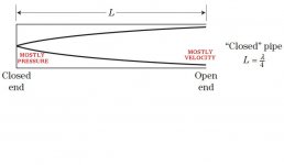
Here is the clever part though , you only need to open up the last part of the path because as you approach the end of the path we are dealing with mostly velocity accompanied by the least amount of pressure (at FB where it is critical) , as opposed to somewhere in the middle of the path where there is a fair mix (less velocity and more pressure) so you can get away with the 2.5" constriction in the middle (S3-ish region) but NOT at the very end (S4/S5) at those high power levels ............................. Then of course at the closed end of the pipe (S1 region) we have mostly pressure and very little velocity(note: I believe that this also has a lot to do with why this S1 area is a good place for adding your fibrous stuffing material without suffering too much loss, because S1 is an area of very low velocity) ...
So the moral of the story is that keeping the constriction at 2.5" in the middle of the path is fine (and keeps you from having to make the box taller in your case) and then opening up the S4/S5 area ( which is the "aperture" in the series tuned Karlflex) can be the secret to your success!

When the main squeeze is in the middle of the path it does change the damping behavior a bit but that should be perfectly fine with those Alpine 10s , they have very strong motors and will respond well to the extra damping ...
This strategy would also be effective for Chriss661 since his Beyma driver prefers an alignment with more damping for a flatter response along with better airflow near the end of path for higher power handling ...
😀
MMJ, I had a sneaking suspicion I was getting too greedy with those Alpines =(
Regarding the particle velocity, would increasing the narrow path area by 0.5-1" worth of width at the expense of path length while using an aperture that maximized path length (lowest possible bottom exit) be helpful enough!? To be fair, my GX5 can only put out 700-800 watts with a 4Ω load so we can use that as a limit!
Sent from my iPhone using Tapatalk
Palsa,
Thats exactly how you could do it 😀
Here is the clever part though
, you only need to open up the last part of the path because as you approach the end of the path we are dealing with mostly velocity accompanied by the least amount of pressure (at FB where it is critical) , as opposed to somewhere in the middle of the path where there is a fair mix (less velocity and more pressure) so you can get away with the 2.5" constriction in the middle (S3-ish region) but NOT at the very end (S4/S5) at those high power levels ............................. Then of course at the closed end of the pipe (S1 region) we have mostly pressure and very little velocity(note: I believe that this also has a lot to do with why this S1 area is a good place for adding your fibrous stuffing material without suffering too much loss, because S1 is an area of very low velocity) ... So the moral of the story is that keeping the constriction at 2.5" in the middle of the path is fine (and keeps you from having to make the box taller in your case) and then opening up the S4/S5 area ( which is the "aperture" in the series tuned Karlflex) can be the secret to your success!
When the main squeeze is in the middle of the path it does change the damping behavior a bit but that should be perfectly fine with those Alpine 10s , they have very strong motors and will respond well to the extra damping ...
This strategy would also be effective for Chriss661 since his Beyma driver prefers an alignment with more damping for a flatter response along with better airflow near the end of path for higher power handling ...
😀
Attachments
Last edited:
Absolutely
I think you are precisely right Freddy ,
With a Karlflex we could get upwards of 400hz upper extension (or more with certain drivers and aperture combinations) , so that would mean that our mid-high tops can be highpassed at 400hz+ allowing us to have much smaller top boxes , giving us a super portable system with tops that could be constructed out of extremely affordable components , a few of the 6" CV surplus drivers from ApexJr could handle a fair amount of power if they were high passed at 400hz or 500hz ..... You could even make short-horn loaded mini line-arrays out of them , very simple but very effective ...

hey GM - so for today's drum tunings a 40Hz LF corner should cover the "sub" (?) where can one find truly stellar recordings of jazz drums, hyper speed double kick metal, etc.? Maybe a reasonable size Karlflex would do nice for a reasonably portable electronic drumkit bottom (- you can tell I'm old and come from a pre-dominant PA era when each instrument pretty much stood alone on the stage) what inexpensive but loud drivers could one use with a passive crossover on top for the critical midrange? (MMJ has those bargain CV.)
I think you are precisely right Freddy ,
With a Karlflex we could get upwards of 400hz upper extension (or more with certain drivers and aperture combinations) , so that would mean that our mid-high tops can be highpassed at 400hz+ allowing us to have much smaller top boxes , giving us a super portable system with tops that could be constructed out of extremely affordable components , a few of the 6" CV surplus drivers from ApexJr could handle a fair amount of power if they were high passed at 400hz or 500hz ..... You could even make short-horn loaded mini line-arrays out of them , very simple but very effective ...
Attachments

Holy crap XRK thank you for that! Sketch and all! That's about double the power I could throw at it for now. I will have to work out a design and further look at some dimension first as well but looks freakin awesome!
MMJ I'll have to make a new drawing in that case! Thanks for the info!'
Sent from my iPhone using Tapatalk
MMJ I'll have to make a new drawing in that case! Thanks for the info!'
Sent from my iPhone using Tapatalk
Holy crap XRK thank you for that! Sketch and all! That's about double the power I could throw at it for now. I will have to work out a design and further look at some dimension first as well but looks freakin awesome!
MMJ I'll have to make a new drawing in that case! Thanks for the info!'
Sent from my iPhone using Tapatalk
C&P,
You are welcome - it was fun to get some akabak going again and it confirmed my suspicion that the XKi really controls cone motion well. This sub is not excursion limited but rather power thermal limited and velocity vent compression limited. I have not worked out box dimensions but probably 5 cu ft external volume with wood thickness and vent volume (assuming 0.5in for vent walls).
- Home
- Loudspeakers
- Subwoofers
- New sub design? Constricted Transflex, simple build (series tuned 6th order)