
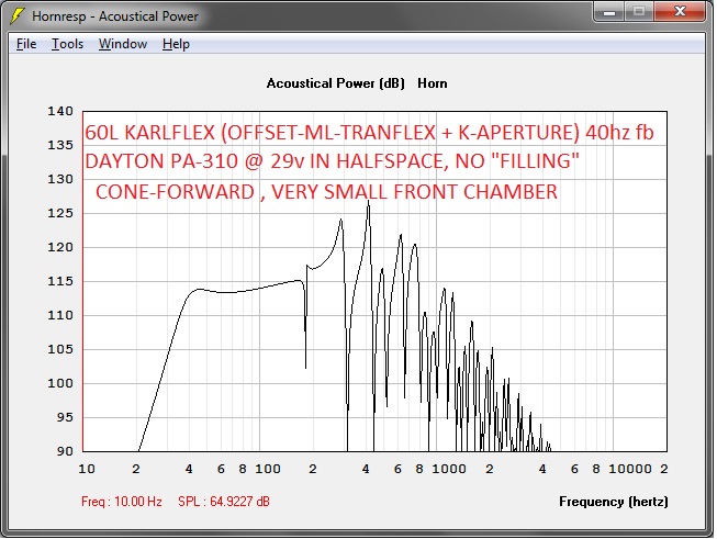
so a small and lightweight PA stack might be the 60l Karlflex with PA310, 2->4 CV 6" with simple waveguide (or other bargain hi-sensitivity mid) , 4-1016 Frankenpiezo, all tied together with a modest priced passive crossover
so a small and lightweight PA stack might be the 60l Karlflex with PA310, 2->4 CV 6" with simple waveguide (or other bargain hi-sensitivity mid) , 4-1016 Frankenpiezo, all tied together with a modest priced passive crossover
Freddi,
That sounds about right! =) Those CV drivers do work well on a short waveguide or even a short front loaded horn .. I am sure the crossover point can be very high depending on how high the PA-310 Karlflex plays reliably , so lets sayy ohh maybe a crossover point of 500hz or so those CV mids should take quite a bit of power and last a long time ...
It seems that a 1:1 ratio of XFMR driven FrankenPiezos to CV mids is reasonable ... Crossover could be kept very simple and affordable, after all a single series cap for the XFMR driven Frankens is all that is needed on the high pass side 🙂 , on the low pass side with the 310s a 2nd order network should filter well enough ...
Last edited:
FOR THE LOVE OF THE HOLY GOATS!!!!
 GENTLEMEN ,
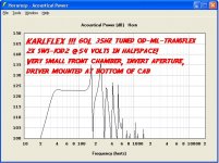
Take a look at what happens when we put two SWS-10D drivers into this cabinet!!!

That sim is in halfspace, but if you want to place this cab into a corner or in your car or SUV just add 10 decibels to that graph!!
These SWS 10" drivers aren't terribly expensive, so this makes a great dollar per decibel value!! Not to mention the relatively lilliputian cabinet size! ...
You could install a handle and carry one of these Dual 10 Karlflex cabinets around like a big briefcase using one arm!
This combination is going to be pretty tough to beat for the price, size and simplicity 😀
What say ye?
WHAT KIND OF SORCERY IS THIS?!?!?!
😉 I apologize for the excessive use of emoticons, but i am feeling sort of emotional right now...

P.S. just two of these cabinets (60L net each) gets you very close to 130db in halfspace or almost 140db in 1/8th space (.5 pi)
GENTLEMEN , Take a look at what happens when we put two SWS-10D drivers into this cabinet!!!
That sim is in halfspace, but if you want to place this cab into a corner or in your car or SUV
just add 10 decibels to that graph!!These SWS 10" drivers aren't terribly expensive, so this makes a great dollar per decibel value!! Not to mention the relatively lilliputian cabinet size! ...
You could install a handle and carry one of these Dual 10 Karlflex cabinets around like a big briefcase using one arm!
This combination is going to be pretty tough to beat for the price, size and simplicity 😀
What say ye?
WHAT KIND OF SORCERY IS THIS?!?!?!
😉 I apologize for the excessive use of emoticons, but i am feeling sort of emotional right now...
P.S. just two of these cabinets (60L net each) gets you very close to 130db in halfspace or almost 140db in 1/8th space (.5 pi)
Attachments
Last edited:
Thanks for spreading the good word about the dual SWS's! I'd rather these guys see it from you! Haha that's an absolutely diabolical smooth cab for it's size! And what I like is that I can wire it to 4ohm to squeeze the most out of my GX5 until I get a bigger amp. I shall shortly whip up a Solidworks model with handle included for all to share! What guidelines shall I follow on the Karflex aperture? From what I can tell it's a pair of tangent arcs terminating at the bottom corners starting from a shared point at the midpoint of the top of the cab. Will include provisions for removable aperture.
Thanks!
Sent from my iPhone using Tapatalk
Thanks!
Sent from my iPhone using Tapatalk
Hopefully at least as clear as mud .....
Diabolically smooth !! I like that! hehehehe
A solidworks model would be great!
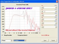
About the K-Aperture and the inverted version of the K-Aperture , i will attempt to explain , your terminology is eloquent so i will go with that ....
Originally i had attempted to sim this cabinet using an orientation of the K-Aperture that is similar to both the Karlsonator and the XKi which are both (mostly) series tuned and have the (as you say) "shared" or meeting point of the tangent arcs at the top end of the cabinet's front where the constriction vents into the forward chamber and that works well for many drivers (for example that is probably the way to go with the PA-310) however if you turn the K-Aperture upside down it ends up converting the alignment into more of a parallel tuned bandpass but still with some tapped effect since both the main pipe and our small front chamber share a mouth (terminus, Aperture, or whatever you want to call it) and this parallel-tuned arrangment works better for drivers like the Lab12 , Alpine's SWS line , and the surplus Rockford Fosgate 10s from ApexJr ..... It can correct any over-offset condition and lifts up the midband response ... You can witness the effect for yourself by adjusting the "VRC" from 0 liters to 10 liters in the Fosgate or Alpine sims that i posted most recently, the changes in midband response are substantially improved but upper bandpass cutoff is lowered to something closer to the useful upper range of these particular drivers ...
This alignment could also be called an offset ML-compound horn/pipe/QWT , or offset compound tapped ML-TL , or who knows what else but i think the name KARLFLEX is most catchy !
P.S. A person wouldn't even necessarily have to use the classic Karlson Aperture shape, other shapes can be tried as well based upon their particular requirements or applications .... Someone could even make a front panel with carefully adjusted venting on BOTH the top and bottom , giving the cabinet an interesting mix of parallel and series tuned characteristics (similar to one of the 8th order Badass-Bandpass sketches i posted recently) ... We could call it the "DOUBLE ENDER"! 😉
hehehehe
Thanks for spreading the good word about the dual SWS's! I'd rather these guys see it from you! Haha that's an absolutely diabolical smooth cab for it's size! And what I like is that I can wire it to 4ohm to squeeze the most out of my GX5 until I get a bigger amp. I shall shortly whip up a Solidworks model with handle included for all to share! What guidelines shall I follow on the Karflex aperture? From what I can tell it's a pair of tangent arcs terminating at the bottom corners starting from a shared point at the midpoint of the top of the cab. Will include provisions for removable aperture.
Thanks!
Sent from my iPhone using Tapatalk
Diabolically smooth !! I like that! hehehehe
A solidworks model would be great!
About the K-Aperture and the inverted version of the K-Aperture , i will attempt to explain , your terminology is eloquent so i will go with that ....
Originally i had attempted to sim this cabinet using an orientation of the K-Aperture that is similar to both the Karlsonator and the XKi which are both (mostly) series tuned and have the (as you say) "shared" or meeting point of the tangent arcs at the top end of the cabinet's front where the constriction vents into the forward chamber and that works well for many drivers (for example that is probably the way to go with the PA-310) however if you turn the K-Aperture upside down it ends up converting the alignment into more of a parallel tuned bandpass but still with some tapped effect since both the main pipe and our small front chamber share a mouth (terminus, Aperture, or whatever you want to call it) and this parallel-tuned arrangment works better for drivers like the Lab12 , Alpine's SWS line , and the surplus Rockford Fosgate 10s from ApexJr ..... It can correct any over-offset condition and lifts up the midband response ... You can witness the effect for yourself by adjusting the "VRC" from 0 liters to 10 liters in the Fosgate or Alpine sims that i posted most recently, the changes in midband response are substantially improved but upper bandpass cutoff is lowered to something closer to the useful upper range of these particular drivers ...
This alignment could also be called an offset ML-compound horn/pipe/QWT , or offset compound tapped ML-TL , or who knows what else but i think the name KARLFLEX is most catchy !
P.S. A person wouldn't even necessarily have to use the classic Karlson Aperture shape, other shapes can be tried as well based upon their particular requirements or applications .... Someone could even make a front panel with carefully adjusted venting on BOTH the top and bottom , giving the cabinet an interesting mix of parallel and series tuned characteristics (similar to one of the 8th order Badass-Bandpass sketches i posted recently) ... We could call it the "DOUBLE ENDER"! 😉
hehehehe
Attachments
Last edited:
the aperture might even be lemon-flavored 😀 (a tribute to the RJ enclosure) - that was symmetrically fed
slimline RJ-12
slimline RJ-12
An externally hosted image should be here but it was not working when we last tested it.
MMJ, your twin SWS plot looks much flatter than mine. Did you just swap the TS parameters into HR or were there other changes made? If so would you mind discussing these changes?
Also, are you saying we can get away with a QSC KSUB style aperture turned 90 degrees!?
Sent from my iPhone using Tapatalk
Also, are you saying we can get away with a QSC KSUB style aperture turned 90 degrees!?
Sent from my iPhone using Tapatalk
I'm suspicious of graphs that nice. What's the port exit velocity?
Something tells me you're going to hit serious port compression and lose output.
That said, I'm (not-so-) secretly hoping a Beyma 15P1200Nd will do 35Hz at PA levels in one of these. I've a pair of these drivers around and THs are just a bit on the big side...
Chris
Something tells me you're going to hit serious port compression and lose output.
That said, I'm (not-so-) secretly hoping a Beyma 15P1200Nd will do 35Hz at PA levels in one of these. I've a pair of these drivers around and THs are just a bit on the big side...
Chris
Lovely organic shape
Freddi ,
It looks some builder chose to combine their love for citrus fruit and vintage speaker cabinets!
😛
Freddi ,
It looks some builder chose to combine their love for citrus fruit and vintage speaker cabinets!
😛
the aperture might even be lemon-flavored 😀 (a tribute to the RJ enclosure) - that was symmetrically fed
slimline RJ-12
An externally hosted image should be here but it was not working when we last tested it.
Attachments
CREATIVE MOUTHING
Yes exactly , that QSC sub's aperture turned 90 degrees (and it could even possibly be oriented as seen in the picture but perhaps we should avoid vents with an overly extreme aspect ratio) ...... The "double ended" 🙂p) approach would just basically give you a small terminus or slot vent at the top and bottom with equal area .... Adjust the area of those two slot vents to dial in your FB .... This approach is a little bit interesting because it blends both parallel and series tuned alignments ..............................
The opposite approach could also be tried meaning that a single opening (mouth/aperture/terminus) (with area equal to or as little as half of the driver's SD) in the front panel could be located somewhat between the top and bottom , the lower you place the aperture the longer it will make the main path which in turn lowers the FB, and then likewise the higher you move that aperture the higher the FB will shift BUT also giving you more of that wonderful Parallel tuned "VRC" chamber action that works so fantastically for our car audio styled drivers and the Lab12 ..
PALSA , did you increase the LE figure on your SWS10d in sim? It is something i normally do, changes the curve a little, gets us a little closer to what real world measurements will be .... Try using an LE value of 3.7 for the two voicecoils in series (3.6 ohm dc re) with the SWS-10D2🙂
MMJ, your twin SWS plot looks much flatter than mine. Did you just swap the TS parameters into HR or were there other changes made? If so would you mind discussing these changes?
Also, are you saying we can get away with a QSC KSUB style aperture turned 90 degrees!? View attachment 463840
Sent from my iPhone using Tapatalk
Yes exactly , that QSC sub's aperture turned 90 degrees (and it could even possibly be oriented as seen in the picture but perhaps we should avoid vents with an overly extreme aspect ratio) ...... The "double ended" 🙂p) approach would just basically give you a small terminus or slot vent at the top and bottom with equal area .... Adjust the area of those two slot vents to dial in your FB .... This approach is a little bit interesting because it blends both parallel and series tuned alignments ..............................
The opposite approach could also be tried meaning that a single opening (mouth/aperture/terminus) (with area equal to or as little as half of the driver's SD) in the front panel could be located somewhat between the top and bottom , the lower you place the aperture the longer it will make the main path which in turn lowers the FB, and then likewise the higher you move that aperture the higher the FB will shift BUT also giving you more of that wonderful Parallel tuned "VRC" chamber action that works so fantastically for our car audio styled drivers and the Lab12 ..
PALSA , did you increase the LE figure on your SWS10d in sim? It is something i normally do, changes the curve a little, gets us a little closer to what real world measurements will be .... Try using an LE value of 3.7 for the two voicecoils in series (3.6 ohm dc re) with the SWS-10D2🙂
I had the same thoughts about velocity
Chris ,
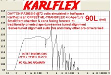
That graph does look particularly flat for those two Alpine 10s in the 60l box , not all other drivers had such a flat curve, the Alpines just happened to work out well ...
And Yes, i was concerned with air particle velocity as well especially with these multiple high XMAX drivers at such high power levels and a mass loading section with an area of only around 200 sq cm, but according to Hornresponse's handy velocity graph everything is within acceptably safe bounds ..................................... On a related issue, our slot vent style mass loading (port) has an aspect ratio of 5.5:1 which is well below the risky 9:1 or more ratio (a generally accepted rule-of-thumb for slot vents) so that design facet is also within acceptable bounds...
Chris,
I can scale up the 60 liter box to 90 liters or 100 liters and sim your 15" Beyma
Do you have measured T/S parameters for that driver or would you like me to just use the published specs?
Let me know 🙂
I'm suspicious of graphs that nice. What's the port exit velocity?
Something tells me you're going to hit serious port compression and lose output.
That said, I'm (not-so-) secretly hoping a Beyma 15P1200Nd will do 35Hz at PA levels in one of these. I've a pair of these drivers around and THs are just a bit on the big side...
Chris
Chris ,
That graph does look particularly flat for those two Alpine 10s in the 60l box , not all other drivers had such a flat curve, the Alpines just happened to work out well ...
And Yes, i was concerned with air particle velocity as well especially with these multiple high XMAX drivers at such high power levels and a mass loading section with an area of only around 200 sq cm, but according to Hornresponse's handy velocity graph everything is within acceptably safe bounds ..................................... On a related issue, our slot vent style mass loading (port) has an aspect ratio of 5.5:1 which is well below the risky 9:1 or more ratio (a generally accepted rule-of-thumb for slot vents) so that design facet is also within acceptable bounds...
Chris,
I can scale up the 60 liter box to 90 liters or 100 liters and sim your 15" Beyma
Do you have measured T/S parameters for that driver or would you like me to just use the published specs?
Let me know 🙂
Oh no! While cadding up the box I realized those planning on using 2 SWS10's might want to make a slight change to the cab!

Using the dims provided in Apline's manual, it looks like the cab might need to be made an inch taller overall!
For me, with a few spare sheets of 5x5 BB in the garage this is no problem, It may change things efficiency wise for you guys working with 4x8's however.
Growing the cab that extra vertical inch looks like it will allow the drivers to just fit on the baffle!

Hopefully all this will do is make lower Fb slightly.
Let me know if you guys want some more models!
Sent from my iPhone using Tapatalk
Using the dims provided in Apline's manual, it looks like the cab might need to be made an inch taller overall!
For me, with a few spare sheets of 5x5 BB in the garage this is no problem, It may change things efficiency wise for you guys working with 4x8's however.
Growing the cab that extra vertical inch looks like it will allow the drivers to just fit on the baffle!
Hopefully all this will do is make lower Fb slightly.
Let me know if you guys want some more models!
Sent from my iPhone using Tapatalk
Oh yes, I see now,
Well if it has to be 25" tall for two 10" drivers then that is fine , the FB can be dialed-in with changes to the front panel anyhow .... Not so awesome for folks who use 4x8 sheets, but hey, the 24" H box still works for single 12s and 15s (scaled up width) or even an 18! (scaled up as a 24" cube) so there are still lots of sheet-efficient options for builders🙂

For the dual 10s box, the extra inch of height could be added to the very first section of the vent/constriction (the first 6 or 7 inches of it before the constriction's first turn) making it 3.5" high instead of 2.5" then that would provide a smoother transition between the larger area of the early path and the smaller area of the latter part of the path , essentially making this a 3 step tapered path versus 2 step, and the shift in FB would compensate for the increased path length due to the extra height of the box 😀
Well if it has to be 25" tall for two 10" drivers then that is fine , the FB can be dialed-in with changes to the front panel anyhow .... Not so awesome for folks who use 4x8 sheets, but hey, the 24" H box still works for single 12s and 15s (scaled up width) or even an 18! (scaled up as a 24" cube) so there are still lots of sheet-efficient options for builders🙂
For the dual 10s box, the extra inch of height could be added to the very first section of the vent/constriction (the first 6 or 7 inches of it before the constriction's first turn) making it 3.5" high instead of 2.5" then that would provide a smoother transition between the larger area of the early path and the smaller area of the latter part of the path , essentially making this a 3 step tapered path versus 2 step, and the shift in FB would compensate for the increased path length due to the extra height of the box 😀
Last edited:
Ok, here we go, 15" drivers in the cone-forward Karlflex!
For your viewing pleasure (and potentially your future listening pleasure) here are a few 15" drivers in the KARLFLEX (cone forward version) .. These are both of course based upon the layout in the attached sketch and scaled up to 90L with 19" width.
The Lab15 (like many other heavy drivers that were meant to be strictly subs) prefers the Invert-Aperture (a parallel alignment) and the sim file is set up that way with some "VRC" and very little flare at the end of the main path, it uses roughly half the driver's SD as the shared (tapped) terminus/aperture area ...
The Dayton PA385S-8 prefers the K-aperture to be oriented just as it would be in the XKi or the Karlsonator (series tuned) and the sim posted here for the Dayton reflects that alignment (no VRC , and the end of the main path is flared significantly ending with an area roughly equaling the driver's SD) ...
So this gives you both a series tuned Karflex alignment sim and also a Parallel tuned Karflex alignment sim with the Invert-Aperture, so you can plug other 15" drivers into both alignments to see which one works better for your particular driver .. 😀
Attachments
-
KFLXPA385S90.txt1,007 bytes · Views: 66
-
KFLXL154S90L.txt1,005 bytes · Views: 68
-
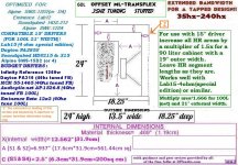 OFFSET ML-TRANSFLEX -35hz-60L-LAB12-OR-SWS-12D-24inch-150-cm 40hz or 160cm 35hz Path-Small-Front.jpg241.7 KB · Views: 297
 -
 OFFSET ML-TRANSFLEX -35hz-90L-DAYTON PA-385S-8-- 72V-HALFSPACE---24inch- 35hz Path-Small-Front-C.JPG178.3 KB · Views: 288
 -
 OFFSET ML-TRANSFLEX -35hz-90L-LAB15-4-SPECIAL 63V-HALFSPACE---24inch- 35hz Path-Small-Front-Cham.JPG203.8 KB · Views: 292
Last edited:
FWIW, I simmed a Beyma 15P1200Nd in the PA385S enclosure. 2.83v sensitivity is around 94dB. Hitting it with the full 1200w thermal power handling gives 30mm p/p excursion, and around 125dB.
Seems pretty similar to a ported box IMHO...
Any ideas what the Karlson slot on the front would do to the response?
Chris
Seems pretty similar to a ported box IMHO...
Any ideas what the Karlson slot on the front would do to the response?
Chris
when enclosures are the same overall size and same general tuning, it can be "six of one vs half dozen of the other" 😀 Are both cases impedance curves identical? sometimes a tapped pipe gives a better vent.
Posts #1018/1035
Hi Y'all,
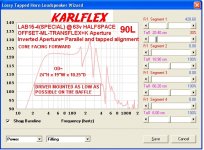
I worked a little on the KARLFLEX w/ the SWS 10D2, and it looks pretty good (I'm not sure about the T/S parameters.). There are some areas where the drivers will choke the duct a little, and the Karlson aperture cannot be simulated in Hornresp, so I'm just using a circular opening in front of the bottom driver. Reducing the mouth opening and increasing L45 a bit would flatten out the response even more, but it's questionable what that will look like @ full power. Build and measure. What I simulated is basically a T-TQWT w/ a (round port) Karlson terminus. It needs very little filling in the L12 area.
The driver mounting baffle should be build from two layers of 1/2" plywood (at least); that way the drivers can be inserted a little deeper. This will not change the simulation much at all. A little bracing would not hurt. 1/2" ply for this type of box sounds a little light, but I guess that's the idea.
Regards,
Hi Y'all,
I worked a little on the KARLFLEX w/ the SWS 10D2, and it looks pretty good (I'm not sure about the T/S parameters.). There are some areas where the drivers will choke the duct a little, and the Karlson aperture cannot be simulated in Hornresp, so I'm just using a circular opening in front of the bottom driver. Reducing the mouth opening and increasing L45 a bit would flatten out the response even more, but it's questionable what that will look like @ full power. Build and measure. What I simulated is basically a T-TQWT w/ a (round port) Karlson terminus. It needs very little filling in the L12 area.
The driver mounting baffle should be build from two layers of 1/2" plywood (at least); that way the drivers can be inserted a little deeper. This will not change the simulation much at all. A little bracing would not hurt. 1/2" ply for this type of box sounds a little light, but I guess that's the idea.
Regards,
Attachments
- Home
- Loudspeakers
- Subwoofers
- New sub design? Constricted Transflex, simple build (series tuned 6th order)