Some reasons for offset
Your schooling sounds like it could involve some intense engineering!
Alright , i will gladly explain to you a few things that i know about in regards to this sort of significant offset, im sure there is even more to it but this is just my understanding......
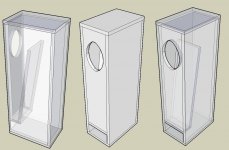
It is first imperative to understand that pipes with one closed end (which is most of the "quarterwave" designs that i can think of) have strong resonances not only at the fundamental but also at the odd harmonics, with the 3rd and 5th harmonics concerning us the most because they add so much "ripple" to the response to such an extent that it can severely limit the useful bandwidth of the design ..........What is an answer to this problem?.... BEHOLD the offset solution! 😛 -------> You can very effectively suppress the 3rd harmonic by shifting the driver's position significantly down the path to around 1/3 from the closed end (+ or - depending on design) .... This often allows useful output to extend out to the 5th harmonic which is verifiable in Hornresponse 🙂
It is important to note that the 3rd and 5th harmonics don't always end up exactly at F*3 and F*5 because the use of an expansion tends to shift the harmonics downward in relation to the fundamental, on the contrary a taper or Mass-loading (one in the same really) pushes the harmonics higher up in relation to the fundamental .... This phenomenon is also verifiable in Hornresponse 🙂 ...
Something else to keep in mind about this sort of 1/3-ish path offset is the fact that you are moving the driver away from the zone of highest pressure (highest pressure occurs at the closed end of the pipe @ or around the fundamental) and because you are moving the driver into an area of less pressure the nature of the system's damping changes, and it becomes less damped in this case ................... Underdamped systems have saddle shaped responses with peaks at the resonances, overdamped systems have hump shaped responses with relative losses at the fundamental ................ Making a box smaller can increase the damping of the system, so in our OD-ML-TRANSFLEX scenario we have offset the driver significantly which reduced the system damping and then we compensate by reducing the cabinet size in order to become reasonably damped again so we can regain a somewhat flat response .... These damping effects that i am ranting about are also verifiable in Hornresponse.. 🙂
I also have to say that i really appreciate the fact that we can add stuffing to the closed end of an 1/3rd-ish offset system without suffering too much loss at the fundamental (something you cannot really do with a typical tapped horn without suffering lossiness in the wrong places) but the fibrous stuffing does a great job at taming the peaks and flattening response in these offset systems ....... This is one of the great advantages to using this sort of design ... Having this much offset allows the stuffing (at the closed end) to be beneficial without also being overly detrimental, now is that about as clear as mud? 🙄 haha ok ........ HR's new "filling" feature can be used to verify the effects of using fibrous stuffing material at the closed end of these heavily offset systems.. 🙂
The moral of the story is Hornresponse is some incredibly smart software!!
Unfortunately as clever as it is Hornresponse doesn't perfectly simulate an OD-ML-TRANSFLEX due to the need for more segments to work with and also the fact that offsets within the throat chamber are not allowed which creates a technical dilemma when trying to simulate these sort of cabinets ..... I have found ways to improvise but i will have to cover that in my next post because this post is already too long ...
Good information to take in! This may not be for a while, School is starting back up and this looks like a whopper of a semester. Lots of heat transfer, thermo, and machine design 😱
MMJ, Do you have a set of HR inputs for that awesome looking box? And if it isn't too complicated to explain, what does the offset do for the response?
Your schooling sounds like it could involve some intense engineering!
Alright , i will gladly explain to you a few things that i know about in regards to this sort of significant offset, im sure there is even more to it but this is just my understanding......
It is first imperative to understand that pipes with one closed end (which is most of the "quarterwave" designs that i can think of) have strong resonances not only at the fundamental but also at the odd harmonics, with the 3rd and 5th harmonics concerning us the most because they add so much "ripple" to the response to such an extent that it can severely limit the useful bandwidth of the design ..........What is an answer to this problem?.... BEHOLD the offset solution! 😛 -------> You can very effectively suppress the 3rd harmonic by shifting the driver's position significantly down the path to around 1/3 from the closed end (+ or - depending on design) .... This often allows useful output to extend out to the 5th harmonic which is verifiable in Hornresponse 🙂
It is important to note that the 3rd and 5th harmonics don't always end up exactly at F*3 and F*5 because the use of an expansion tends to shift the harmonics downward in relation to the fundamental, on the contrary a taper or Mass-loading (one in the same really) pushes the harmonics higher up in relation to the fundamental .... This phenomenon is also verifiable in Hornresponse 🙂 ...
Something else to keep in mind about this sort of 1/3-ish path offset is the fact that you are moving the driver away from the zone of highest pressure (highest pressure occurs at the closed end of the pipe @ or around the fundamental) and because you are moving the driver into an area of less pressure the nature of the system's damping changes, and it becomes less damped in this case ................... Underdamped systems have saddle shaped responses with peaks at the resonances, overdamped systems have hump shaped responses with relative losses at the fundamental ................ Making a box smaller can increase the damping of the system, so in our OD-ML-TRANSFLEX scenario we have offset the driver significantly which reduced the system damping and then we compensate by reducing the cabinet size in order to become reasonably damped again so we can regain a somewhat flat response .... These damping effects that i am ranting about are also verifiable in Hornresponse.. 🙂
I also have to say that i really appreciate the fact that we can add stuffing to the closed end of an 1/3rd-ish offset system without suffering too much loss at the fundamental (something you cannot really do with a typical tapped horn without suffering lossiness in the wrong places) but the fibrous stuffing does a great job at taming the peaks and flattening response in these offset systems ....... This is one of the great advantages to using this sort of design ... Having this much offset allows the stuffing (at the closed end) to be beneficial without also being overly detrimental, now is that about as clear as mud? 🙄 haha ok ........ HR's new "filling" feature can be used to verify the effects of using fibrous stuffing material at the closed end of these heavily offset systems.. 🙂
The moral of the story is Hornresponse is some incredibly smart software!!
Unfortunately as clever as it is Hornresponse doesn't perfectly simulate an OD-ML-TRANSFLEX due to the need for more segments to work with and also the fact that offsets within the throat chamber are not allowed
which creates a technical dilemma when trying to simulate these sort of cabinets ..... I have found ways to improvise but i will have to cover that in my next post because this post is already too long ...Matthew, wow great explanation, in my nubie mind are there any materials that have been tested and verified to absorb specific frequency? I do not mean overall dampening but more specific....
Wow that's a solid understanding you've got there! pretty cool how offset and undersized cabinets give favorable response =)
Now I just need to figure out how to overnight a 6 of craft beer to Xrk for simming the OD-ML-TRANSFLEX in AkAbak for us =P If that cabinet is true to the Sim it looks like the best way to get a reliable 117dB from a LAB12 in 80L down to high 30's! That's before I stuff it in a corner =)
Now I just need to figure out how to overnight a 6 of craft beer to Xrk for simming the OD-ML-TRANSFLEX in AkAbak for us =P If that cabinet is true to the Sim it looks like the best way to get a reliable 117dB from a LAB12 in 80L down to high 30's! That's before I stuff it in a corner =)
Matthew, wow great explanation, in my nubie mind are there any materials that have been tested and verified to absorb specific frequency? I do not mean overall dampening but more specific....
I don't really know, maybe, I have always just used fiberglass and fine poly-fiberfil .... I have even used poly fiber sheets to make a pillow stuffed full of dryer lint
 , it actually worked well 😀
Other offset examples
These sorts of offsets are nothing new by the way .... They have been used for a long time, just usually not with the tapped variety of designs ...
Here are some examples of other people's designs with offsets ...... Many of these are mass loaded as well .... Between the offset and the stuffing these pipe's harmonic ripples are reduced enough to allow these guys to use the full bandwidth of the driver ...
"Spanning" a bunch of drivers along the line can also give you an offset effect and is thought (assumed) to have additional benefits regarding spreading some resonances around and making the drivers seem like they have a slightly lower Q , allowing an even smaller box or more drivers stuffed into the same box but i haven't been able to confirm that for sure even though i have built a few spanned boxes with high Q drivers and i did like their sound despite the uber cheap drivers i happened to use in those experiments 😛
Attachments
-
 3.jpg5 KB · Views: 242
 -
 VP1.jpg70.7 KB · Views: 107
 -
 tqwt2.gif15.7 KB · Views: 108
 -
 tl-sietse.jpg29.3 KB · Views: 114
 -
 mileva-FE127-MLV-0v99.gif90.1 KB · Views: 106
 -
 Latest Jeschke Voight Pipe.jpg60.8 KB · Views: 112
 -
 img6.gif36.7 KB · Views: 219
 -
 C. Joye voigt2 schematic.jpg18.8 KB · Views: 221
 -
 box_qwt.jpg4.6 KB · Views: 215
 -
 550thtaper_su.png14.6 KB · Views: 226
Last edited:
Unfortunately as clever as it is Hornresponse doesn't perfectly simulate an OD-ML-TRANSFLEX due to the need for more segments to work with and also the fact that offsets within the throat chamber are not allowed which creates a technical dilemma when trying to simulate these sort of cabinets ..... I have found ways to improvise but i will have to cover that in my next post because this post is already too long
More segments ? No problem! Try akabak you can have about 50 segments. Really flexible and powerful once you get the hang of it. Because it is script based, reuse of segments of code is possible so you can build complex speakers from existing blocks of your old code.
More segments ? No problem! Try akabak you can have about 50 segments. Really flexible and powerful once you get the hang of it. Because it is script based, reuse of segments of code is possible so you can build complex speakers from existing blocks of your old code.
X ,
Yeah, you are right, I need to make learning Akabak a priority here in the near future ...
Wow that's a solid understanding you've got there! pretty cool how offset and undersized cabinets give favorable response =)
Now I just need to figure out how to overnight a 6 of craft beer to Xrk for simming the OD-ML-TRANSFLEX in AkAbak for us =P If that cabinet is true to the Sim it looks like the best way to get a reliable 117dB from a LAB12 in 80L down to high 30's! That's before I stuff it in a corner =)
Thanks! and Yes! 🙂
Would XRK do it for beer? That would be great 🙂
Palsa , i actually got the box size down to about 60 liters net which is pretty darn small for such a thing, it will be really interesting to see how it competes with your larger reflex box ... In simulations it shows an advantage of 3db right? I am looking forward to seeing your measurements and hearing about your listening impressions too ..
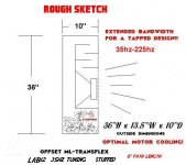
When you are ready to build let me know and i will crank out a more detailed sketch ....
Equivalents and analogs for OD-ML-Transflex
Palsa,
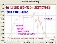
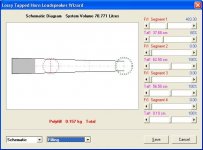
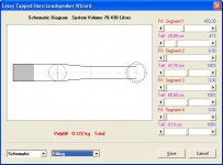
In the meantime , take a look at these approximated equivalent HR sims ..... Like i had said before these extremely long bass waves don't really know the difference between a drawn out tapered style mass loading scheme or abrupt steps, they pretty accomplish the same results and response ends up being pretty much the same (for an identical cabinet size and tuning of course) ...
At the smallest point in the path i found that it is best not to go any smaller than about 200cm sq (with this driver and arrangement) or the particle velocity is increased too much .... So i'm sticking with 200sq cm at the point of greatest constriction which still keeps this cab's particle velocity rating below that of Saba's Alpine ML-Transflex cab (which never had any issues with chuffing at full power) so i feel confident that it is within the safe range for this type of design...
Note:
The tiny chamber (VRC & LRC) i threw onto these sims was an attempt to emulate the effects that the shared (series and parallel) mouth chamber would have upon loading in the midbass range, so there is 10 liters of redundant space in the sim that doesn't need to be figured into the actual box build which is 60 liters net , not 70 ....
You can see one schematic is stepped , the other is just a taper .... Response is the same for both ......
Driver tap is located halfway out of the end of the box because that is what best simulates our very conservative amount of tapped effect in this ML-Transflex alignment ...
P.S. You have to view the response in "Loudspeaker Wizard" in order to see the effects of the "filling" ...
Palsa,
In the meantime , take a look at these approximated equivalent HR sims ..... Like i had said before these extremely long bass waves don't really know the difference between a drawn out tapered style mass loading scheme or abrupt steps, they pretty accomplish the same results and response ends up being pretty much the same (for an identical cabinet size and tuning of course) ...
At the smallest point in the path i found that it is best not to go any smaller than about 200cm sq (with this driver and arrangement) or the particle velocity is increased too much .... So i'm sticking with 200sq cm at the point of greatest constriction which still keeps this cab's particle velocity rating below that of Saba's Alpine ML-Transflex cab (which never had any issues with chuffing at full power) so i feel confident that it is within the safe range for this type of design...
Note:
The tiny chamber (VRC & LRC) i threw onto these sims was an attempt to emulate the effects that the shared (series and parallel) mouth chamber would have upon loading in the midbass range, so there is 10 liters of redundant space in the sim that doesn't need to be figured into the actual box build which is 60 liters net , not 70 ....
You can see one schematic is stepped , the other is just a taper .... Response is the same for both ......
Driver tap is located halfway out of the end of the box because that is what best simulates our very conservative amount of tapped effect in this ML-Transflex alignment ...
P.S. You have to view the response in "Loudspeaker Wizard" in order to see the effects of the "filling" ...
Attachments
-
 OFFSET ML-TRANSFLEX -35hz-60L-LAB12.JPG43.3 KB · Views: 143
 -
 Halfspace-Lab12-OD-ML-TRANSFLEX-35hz--60L.JPG31.3 KB · Views: 119
 -
L12-ODMLTRV2.txt1,001 bytes · Views: 64
-
L12-ODMLTRV1.txt1,000 bytes · Views: 64
-
 Filling-Tapered-OD-ML-TRANSFLEX-Lab12-35hz-70L.JPG41 KB · Views: 103
 -
 Filling-Stepped-OD-ML-TRANSFLEX-Lab12-35hz-70L.JPG41 KB · Views: 118
Last edited:
Thanks! and Yes! 🙂
Would XRK do it for beer? That would be great 🙂
Palsa , i actually got the box size down to about 60 liters net which is pretty darn small for such a thing, it will be really interesting to see how it competes with your larger reflex box ... In simulations it shows an advantage of 3db right? I am looking forward to seeing your measurements and hearing about your listening impressions too ..
When you are ready to build let me know and i will crank out a more detailed sketch ....
I think I already built skeleton of a ML Transflex model earlier in this thread. You want the new dimensions and the Lab12 ? Point me to the exact post with dimensions. I will see what I can do. I will take drivers over beer if you have a complex specialized sim you want 🙂
Palsa,
In the meantime , take a look at these approximated equivalent HR sims ..... Like i had said before these extremely long bass waves don't really know the difference between a drawn out tapered style mass loading scheme or abrupt steps, they pretty accomplish the same results and response ends up being pretty much the same (for an identical cabinet size and tuning of course) ...
That looks pretty awesome for its size... and if you wouldn't mind, just a few more dims in the pic you posted would be all I need! then a SolidWorks model for everyone would be my duty =)
I think I already built skeleton of a ML Transflex model earlier in this thread. You want the new dimensions and the Lab12 ? Point me to the exact post with dimensions. I will see what I can do. I will take drivers over beer if you have a complex specialized sim you want 🙂
I'm not sure what drivers you need but I can definitely use some LAB12 sim! I will post the TS params and info when the model of the box is complete!
I've found something slightly depressing just now =( it seems there was some discrepancy between WinISD and HornResp. Now that I've simmed my LAB12 bass reflex as-built in the program I am getting this response with an identical 300W input per cab 
It should be noted that the OD ML Transflex (grey trace) is doing it with 20L less and if there is any substantial motor cooling, I might be able to get more power into it. I would still like to build that box! Is there anything wrong here? HR shows my 1W (into 6 Ohm for the LAB) as 91dB at 100Hz and a peak of 93.8dB at 43.5Hz which seems a little optimistic for that driver in a BR...
Sent from my iPhone using Tapatalk
Hi Matthew,
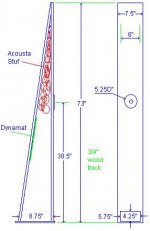
In Post #869: I assume you are using 1/2" plywood, then the actual wall thickness will be 15/32 (.469)" [11.9mm]?
Regards,
In Post #869: I assume you are using 1/2" plywood, then the actual wall thickness will be 15/32 (.469)" [11.9mm]?
Regards,
Hi Matthew,
In Post #869: I assume you are using 1/2" plywood, then the actual wall thickness will be 15/32 (.469)" [11.9mm]?
Regards,
Yessir, thats correct, 1/2" ply .... I usually just figure it to the rounded off .5"
I actually have to revise that sketch in #869 to provide the rest of the details, that will be one of my projects today ...
I've found something slightly depressing just now =( it seems there was some discrepancy between WinISD and HornResp. Now that I've simmed my LAB12 bass reflex as-built in the program I am getting this response with an identical 300W input per cab View attachment 459210
It should be noted that the OD ML Transflex (grey trace) is doing it with 20L less and if there is any substantial motor cooling, I might be able to get more power into it. I would still like to build that box! Is there anything wrong here? HR shows my 1W (into 6 Ohm for the LAB) as 91dB at 100Hz and a peak of 93.8dB at 43.5Hz which seems a little optimistic for that driver in a BR...
Sent from my iPhone using Tapatalk
Palsa,
There have been times when i have had optimistic looking simulations for bass reflex boxes which show great VIRTUAL output around FB , but when actually built and tested have disappointed me .... Unsatisfying .... Didn't live up to the sim for some reason *shrug* ...... Personally i have always had more consistent results with boxes that have at least some amount of useful quarter wave (standing wave or eigenmode) action ..... Which ironically (especially in the ML cases) can be very similar to a bass reflex box with a stretched out aspect ratio ...

I suppose i am probably biased though because i haven't bothered to build or design a strictly helmholtz design in a long time after my last few experiences with them ...
I also tend to stick with drivers that have relatively low VAS figures, higher FS figures, and a Q that isn't terribly low for use in these Transflex and similar designs .... The Lab12's T/S parameters are not what i would consider ideal for these types of boxes but according to sim it will work.. Hopefully it will work as well or better than the larger reflex box but we really wont know for sure until you or someone builds one, listens to it and measures it ...
Today i hope to finish the more detailed sketch 🙂
I can't wait to see it and model it!
Kind of disappointing that I have this LAB12 when many other drivers work better in these quarter wave applications... And to be more specific this OD ML box is actually 24 liters smaller, I'll take all I can get! Now I just need to figure out how to implement a pole mounted 8"+ Horn top with this bass stick without toppling it!!
Sent from my iPhone using Tapatalk
Post #869
Hi Y'all,
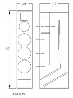
I couldn't make the simulation fit the desired dimensions as in the sketch, but here is my first try at it. You can always reduce the height a tad, or move stuff around inside the box to optimize it, but basically this is it, and w/ a little filling it sims OK. Make sure that the speaker fits through the mouth.
Regards,
Hi Y'all,
I couldn't make the simulation fit the desired dimensions as in the sketch, but here is my first try at it. You can always reduce the height a tad, or move stuff around inside the box to optimize it, but basically this is it, and w/ a little filling it sims OK. Make sure that the speaker fits through the mouth.
Regards,
Attachments
Nice drawing Tb46! If I have time I will sim it as drawn. The driver looks awfully tight in there.
Hi Y'all,
I couldn't make the simulation fit the desired dimensions as in the sketch, but here is my first try at it. You can always reduce the height a tad, or move stuff around inside the box to optimize it, but basically this is it, and w/ a little filling it sims OK. Make sure that the speaker fits through the mouth.
Regards,
WOW !
Good job TB46 , i really like what you did there! 🙂
I was going to give it a shot with 90 degree angles and steps, but yeah , if everything doesn't quite fit right the insides might have to be rearranged a bit or outside dimensions changed a little ....
- Home
- Loudspeakers
- Subwoofers
- New sub design? Constricted Transflex, simple build (series tuned 6th order)