revisions and iterations abundant =P
Tb46 ,
Yeah , that got a little cramped around the mouth area, but hey, check out this iteration using your fantastically spacious outer dimensions (some compensation for internals i assume) , rounded off .... I brought out the front section of the box to meet the 18+ inch requirement allows an extended constricted section without having to use too many turns .... It is simple and as far as i can tell it works , there is a highlighted stub that will extend the path slightly by another inch or two without getting in the way of the driver but it may not be needed .......
The only thing that irks me about this iteration in my rough sketch (attached to this message) is the fact that the mouth chamber is excessively large and that seems wasteful to me .... I have an idea though, I wonder if we could perhaps widen and shorten the box a bit, the extra airspace at S1 would shift the tuning down a bit and allow for a shorter path length ..... I will try to sim ............. The change in dimensions should gobble up the excessive vertical measurement of the mouth chamber ...
Anyway TB46, what do you think of the rough sketch? The extra depth in the mouth chamber would allow for some drivers with deeper motors to be stuffed into there without sticking out and the extra mouth depth also adds to the path length slightly ...
I will load up you HR inputs in the txt file , i didn't realize they changed much other than the offset going to 70-ish cm right?
Hi MMJ,
Here is the remixed version bringing the duct exit to the driver mounting flange. I had to reduce the duct height to 2.47" (this corresponds to 200cm^2 for the cross-section) starting from S3 on out. Seems to work, but whoever builds this will have to trim the last board to make it possible to insert the driver; trimming this will not affect the response. I'll attach the Hornresp simulation too (w/ the understanding that the area around the driver is just an educated guess).
Regards,
P.S.: Post #896: "...Did you have the HR file for that?"
For the one in Post #895 the Hornresp simulation did basically not change.
Tb46 ,
Yeah , that got a little cramped around the mouth area, but hey, check out this iteration using your fantastically spacious outer dimensions (some compensation for internals i assume) , rounded off .... I brought out the front section of the box to meet the 18+ inch requirement allows an extended constricted section without having to use too many turns .... It is simple and as far as i can tell it works , there is a highlighted stub that will extend the path slightly by another inch or two without getting in the way of the driver but it may not be needed .......
The only thing that irks me about this iteration in my rough sketch (attached to this message) is the fact that the mouth chamber is excessively large and that seems wasteful to me .... I have an idea though, I wonder if we could perhaps widen and shorten the box a bit, the extra airspace at S1 would shift the tuning down a bit and allow for a shorter path length ..... I will try to sim ............. The change in dimensions should gobble up the excessive vertical measurement of the mouth chamber ...
Anyway TB46, what do you think of the rough sketch? The extra depth in the mouth chamber would allow for some drivers with deeper motors to be stuffed into there without sticking out and the extra mouth depth also adds to the path length slightly ...
I will load up you HR inputs in the txt file , i didn't realize they changed much other than the offset going to 70-ish cm right?
Attachments

Last edited:
Even more squatty perhaps??
Ok ,
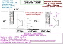
I am testing this in HR sim ..... Adjusting S1 & S2 upward allows for a shorter path down to 165cm now, same tuning, same net volume , response is basically the same..
This means that the cabinet can be made 22" H x 14.5" W x 18.25" D ...... I will go over this a few more times to verify then post a revised rough sketch ...................................................................................................................................... Funny thing is , taken a little bit further (if sim agrees) (such as 20"H x 16.5" W x 18.25" D) would allow us to stuff a 15" driver into this thing! hahaha Of course particle velocity would be out of control with high XMAX 15s , but lighter Pro 15" drivers could work ,they would just need very low VAS figures and very strong motors, seems unlikely .... Maybe the Ciare 15sw.. hmmmm
Ok ,
I am testing this in HR sim ..... Adjusting S1 & S2 upward allows for a shorter path down to 165cm now, same tuning, same net volume , response is basically the same..
This means that the cabinet can be made 22" H x 14.5" W x 18.25" D ...... I will go over this a few more times to verify then post a revised rough sketch ...................................................................................................................................... Funny thing is , taken a little bit further (if sim agrees) (such as 20"H x 16.5" W x 18.25" D) would allow us to stuff a 15" driver into this thing! hahaha Of course particle velocity would be out of control with high XMAX 15s , but lighter Pro 15" drivers could work ,they would just need very low VAS figures and very strong motors, seems unlikely .... Maybe the Ciare 15sw.. hmmmm
Last edited:
Post #869, 878, 891, 895, 897 and 898
Hi MMJ,
I gave it one more try, and reduced the width by 1-1/8". That gets to the point where the combination of basic box response and stuffing starts to either peak like an undersized vented box, or rolls off more than it may be desired. There is a point where the box gets to be too small. You are also at the point where you actually have to draw it in detail to see what you are simulating, there is just not enough leeway. Unless minimum space is paramount I'd go w/ a slightly larger box.
As to Brian's point, the difference between BR (vented box), ML-TL, T-TQWT or these Transflex enclosures seems to be quite small on paper, but people who have build the quarterwave lines like the response. To turn this one into a BR w/ a similarly cross-sectioned duct w/ a similar total volume gets you to a smallish chamber and a long duct, so quite similar.
Regards,
Attachments
Tb46,
Wow that looks like a tight fit for the driver but I like how compact it looks. What does the predicted performance of HR look like?
Wow that looks like a tight fit for the driver but I like how compact it looks. What does the predicted performance of HR look like?
We are so refined =P
Tb46,
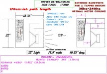
What i meant was a shorter box while keeping the same 60 liters net internal airspace .... I am playing with it right now in Hornresponse .... Making the box wider (im looking at 14.5" outer width) increases the cm sq area at both S1 and S2 , and then it is necessary to resize S4/S5 area back down to between 200 and 220 cm sq which of course tunes the box lower ... Then shortening the box to 22" height puts the FB right back where we started 😀 but with a new path length of only 170cm-ish , so it all works out.......The effective path may end up being more than 170 considering the depth of the mouth chamber now! ......... Everything appears to fit and line up so far ...... Less wasted space in the mouth chamber this time, so i am feeling better about that 🙂
Seems a little less damped (might be of benefit to some drivers) and the upper cutoff moves up slightly, The Alpine really looks great! .... Loudspeaker wizard shows that with filling the FB moves right down to almost exactly 35hz...... The "filling" should also theoretically damp and smooth over the peak in particle velocity as well, to some degree at least ...
Here is a sketch of what i am talking about, and a few sims , one is tapered and the other is semi-stepped (like my sketchy sketches 😛) , results are the same for both ..
Let me know what you think 🙂
Hi MMJ,
I gave it one more try, and reduced the width by 1-1/8". That gets to the point where the combination of basic box response and stuffing starts to either peak like an undersized vented box, or rolls off more than it may be desired. There is a point where the box gets to be too small.
Regards,
Tb46,
What i meant was a shorter box while keeping the same 60 liters net internal airspace .... I am playing with it right now in Hornresponse .... Making the box wider (im looking at 14.5" outer width) increases the cm sq area at both S1 and S2 , and then it is necessary to resize S4/S5 area back down to between 200 and 220 cm sq which of course tunes the box lower ... Then shortening the box to 22" height puts the FB right back where we started 😀 but with a new path length of only 170cm-ish , so it all works out.......The effective path may end up being more than 170 considering the depth of the mouth chamber now! ......... Everything appears to fit and line up so far ...... Less wasted space in the mouth chamber this time, so i am feeling better about that 🙂
Seems a little less damped (might be of benefit to some drivers) and the upper cutoff moves up slightly, The Alpine really looks great! .... Loudspeaker wizard shows that with filling the FB moves right down to almost exactly 35hz...... The "filling" should also theoretically damp and smooth over the peak in particle velocity as well, to some degree at least ...
Here is a sketch of what i am talking about, and a few sims , one is tapered and the other is semi-stepped (like my sketchy sketches 😛) , results are the same for both ..
Let me know what you think 🙂
Attachments

Last edited:
You guys rock! This would work very well for my delta 15...love the smaller size looks dam sweet
results are the same for both ..
Just to clarify, results are basically the same between those sims if using the same driver, however the export file starting with "D12" uses the Alpine and the "L12..." sim uses the Lab
You guys rock! This would work very well for my delta 15...love the smaller size looks dam sweet
Heck yes! ,
This is really coming together!
The Delta will want a larger box to make deep bass, but you could reproduce some great midbass in a fairly compact box.
Almost there
 Alright, almost done with what i am thinking will be my final revision (and less sketchy) sketch for this compact 35hz OD-ML-TRANSFLEX for 12" drivers (and perhaps some 10" drivers if someone really wanted to) ....
Here is a sneak peak!.... Still need to fill in the rest of the internal dimensions (can we call them INFERNAL dimensions? 😛), I may break the smallest part of the path down into two parts instead of one so that "c" would become "c" and "d" , i haven't decided yet ...
It is nice and simple, extremely easy build .....
Looks like there will be at least 2.5" of spare vertical space to be split above and below the driver's frame, and at least an inch to spare horizontally which can be split to give a half inch+ at each side of the frame ...
Added a list of a few more drivers that look acceptable in this box ..... It is really too bad Alpine's SWE series is getting harder to source, as far as a i can tell the supply is drying up ....
Luckily the SWS drivers are still widely available for a great price 🙂 The SWS-12D is really the star performer in this cabinet thus far 😀
TB46 , what do you think of this revision?
Alright, almost done with what i am thinking will be my final revision (and less sketchy) sketch for this compact 35hz OD-ML-TRANSFLEX for 12" drivers (and perhaps some 10" drivers if someone really wanted to) ....Here is a sneak peak!.... Still need to fill in the rest of the internal dimensions (can we call them INFERNAL dimensions? 😛), I may break the smallest part of the path down into two parts instead of one so that "c" would become "c" and "d" , i haven't decided yet ...
It is nice and simple, extremely easy build .....
Looks like there will be at least 2.5" of spare vertical space to be split above and below the driver's frame, and at least an inch to spare horizontally which can be split to give a half inch+ at each side of the frame ...
Added a list of a few more drivers that look acceptable in this box ..... It is really too bad Alpine's SWE series is getting harder to source, as far as a i can tell the supply is drying up ....
Luckily the SWS drivers are still widely available for a great price 🙂 The SWS-12D is really the star performer in this cabinet thus far 😀
TB46 , what do you think of this revision?
Attachments
Last edited:
interesting stuff so far - for "pole" mount I will go coax in this type

NEAT!
A clam right?
Good dispersion and midrange loading from what i have read 🙂
Post #910
Hi MMJ,
I'll try to modify one of the previous drawings to conform to your suggestion in Post #910. It'll be interesting to see the comparison in Hornresp. It'll take me a little time, so maybe tomorrow.
Regards,
Hi MMJ,
I'll try to modify one of the previous drawings to conform to your suggestion in Post #910. It'll be interesting to see the comparison in Hornresp. It'll take me a little time, so maybe tomorrow.
Regards,
further refinement and comparisons
TB46,
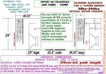
Ok , take a look at what i was working on today.. I proportioned the sketch more accurately and fixed a few other things🙂.. The version that has a 170cm path and 13.5" width seems slightly better suited to the SWS-12D driver .........The 160cm path version at 14.5" width (and more area at S1) provides less control over the particle velocity but the response measures very close to the other ....
I may adjust the sketch to the 170cm 24" tall (13.5"w) version and stick with that, seems marginally superior ..
Notice that i made S2 larger than what is stated in the depiction, it is a little bit of compensation for the depth of the cone .....
.....
I attached both versions so you can compare on your HR ...
Hi MMJ,
I'll try to modify one of the previous drawings to conform to your suggestion in Post #910. It'll be interesting to see the comparison in Hornresp. It'll take me a little time, so maybe tomorrow.
Regards,
TB46,
Ok , take a look at what i was working on today.. I proportioned the sketch more accurately and fixed a few other things🙂.. The version that has a 170cm path and 13.5" width seems slightly better suited to the SWS-12D driver .........The 160cm path version at 14.5" width (and more area at S1) provides less control over the particle velocity but the response measures very close to the other ....
I may adjust the sketch to the 170cm 24" tall (13.5"w) version and stick with that, seems marginally superior ..
Notice that i made S2 larger than what is stated in the depiction, it is a little bit of compensation for the depth of the cone
..... I attached both versions so you can compare on your HR ...
Attachments
Last edited:
References back to Post #869, etc.
Hi MMJ,
I cannot keep up w/ the speed of your flow of ideas. 🙂
So, I converted the drawing from Post #895 into a a wider box w/ your external dimensions from Post #914. I tried to get maximum horn length out of it, but we're well past the point of diminishing returns. At least I was able to stabilize the upper edge of the mouth (that 1/2" material needs a little help, I think). I also tried to get closer w/ the dimensions for the S3-S4-S5 area (see drawing). When moving the sliders around (setting S2 to Auto), I found, that L12=63.4 L23=81.49 would work marginally better, but that doesn't seem to fit the box. This design will need quite a bit of filling.
If I had to build this I'd stay w/ the ~24" high version.
Anyway, this was interesting, and I hope somebody will finish a design, and build/measure a POC, pictures would be nice. 🙂
Regards,
Attachments
This is changing so fast I am afraid to start doing a sim in Akabak for fear it will change. I really like the design and footprint of this last one Tb46. Nice interpretation of the concept. I almost would build it out of XPS foam just to see how it would work but don't have a Lab12. If anyone has a Lab12 to donate to the cause I will build it and measure it.
IF you guys declare that this is the locked down version I will start the akabak model and see if there are any more optimizations to be made.
IF you guys declare that this is the locked down version I will start the akabak model and see if there are any more optimizations to be made.
Hi X,
I think MMJ will still change things around some more. I'm just out of time as far as the drawing is concerned, but it takes an accurate drawing to get accurate Hornresp input data, etc..... 🙂 This one may work better if turned 90 degrees (h=18.25, d=22)?
Regards,
I think MMJ will still change things around some more. I'm just out of time as far as the drawing is concerned, but it takes an accurate drawing to get accurate Hornresp input data, etc..... 🙂 This one may work better if turned 90 degrees (h=18.25, d=22)?
Regards,
Last edited:
Hi MMJ,
I tried to get maximum horn length out of it, but we're well past the point of diminishing returns. At least I was able to stabilize the upper edge of the mouth (that 1/2" material needs a little help, I think).
If I had to build this I'd stay w/ the ~24" high version.
Anyway, this was interesting, and I hope somebody will finish a design, and build/measure a POC, pictures would be nice. 🙂
Regards,
TB46,
I totally agree, the 24" high version seems to be the best way to go with this tuning, format and fold 🙂
I like what you did there with the final bit of the constricted part of the path 🙂
Im finishing up a 24" tall sketch right now
Last edited:
Feeling like we are getting close to final =)
Tb46,
I think your drawings are fully awesome, thank you for taking the time to make those happen, i apologize for the constant revising .... Do you suppose we could crank out one more from you once we have a final revision? 😀
I may experiment with that idea of turning it by 90 degrees ...
Here is my updated sketch for the 24" version, i put more work into trying to make everything match the HR sim more closely (S2 has to be fudged somewhat due to the depth of driver's cone, so that panel doesn't need quite as much angle as initially thought) ..
Things are color coded as follows:
I tried modeling the mouth chamber as an exponential flare at S5 but oddly enough adding the extra 23cm of path length (depth of the mouth) at such an extreme flare rate and nearly 1000 sq cm area at S5 (actually a bit less than that because the driver basket & magnet takes up some of that space) somehow managed to shift the FB upwards slightly ? ?? Which seems entirely counter-intuitive to me, if anything it should have been a downward shift by a hertz or two, because the path is extended by the mouth as it is in series (actually it does double duty because it is a series and parallel "shared" chamber, very Karlsonesque) ........ So anyway, i will just chalk this up to an HR quirk .......... After all when you place a cornerhorn tightly into a corner it doesn't shift the FB upwards, does it? Nevertheless this is "splitting hairs" at this point ..

I am enthused about the fact that a 15" driver fits so well in this sort of layout if it is made a few inches wider, the 4 ohm Lab15 special models well in the 90 liter version , 100 liters would probably be just about right for that driver in this design .... That is 50 liters less than my other (less offset) design for that same driver! 😀
Any thoughts ?
Hi X,
I think MMJ will still change things around some more. I'm just out of time as far as the drawing is concerned, but it takes an accurate drawing to get accurate Hornresp input data, etc..... 🙂 This one may work better if turned 90 degrees (h=18.25, d=22)?
Regards,
Tb46,
I think your drawings are fully awesome, thank you for taking the time to make those happen, i apologize for the constant revising .... Do you suppose we could crank out one more from you once we have a final revision? 😀
I may experiment with that idea of turning it by 90 degrees ...
Here is my updated sketch for the 24" version, i put more work into trying to make everything match the HR sim more closely (S2 has to be fudged somewhat due to the depth of driver's cone, so that panel doesn't need quite as much angle as initially thought) ..
Things are color coded as follows:
- Black= External dimensions
- Fuscia= Internal Dimensions
- Aqua Blue= List of compatible 12" Drivers
- Green= Exciting scale-up data! (can be scaled up by making wider for use with 15s! Maybe even 18s! (but the 18s would have to be really "shoehorned" in because of the vertical constraints)
- Orange= Your cool optional path extension modification.
- Red= Notes and Info
I tried modeling the mouth chamber as an exponential flare at S5 but oddly enough adding the extra 23cm of path length (depth of the mouth) at such an extreme flare rate and nearly 1000 sq cm area at S5 (actually a bit less than that because the driver basket & magnet takes up some of that space) somehow managed to shift the FB upwards slightly ?
?? Which seems entirely counter-intuitive to me, if anything it should have been a downward shift by a hertz or two, because the path is extended by the mouth as it is in series (actually it does double duty because it is a series and parallel "shared" chamber, very Karlsonesque) ........ So anyway, i will just chalk this up to an HR quirk .......... After all when you place a cornerhorn tightly into a corner it doesn't shift the FB upwards, does it? Nevertheless this is "splitting hairs" at this point .. I am enthused about the fact that a 15" driver fits so well in this sort of layout if it is made a few inches wider, the 4 ohm Lab15 special models well in the 90 liter version , 100 liters would probably be just about right for that driver in this design .... That is 50 liters less than my other (less offset) design for that same driver! 😀
Any thoughts ?
Attachments
Last edited:
- Home
- Loudspeakers
- Subwoofers
- New sub design? Constricted Transflex, simple build (series tuned 6th order)