Hi Zen Mod,
That is one that everyone with any amp needs, the principles apply to all. I have it in my repair archives.
Funny thing, when I used to repair Threshold Amps, just because I could, most of the time it was to remove someone's non-factory mod to them that didn't make sense. The Amps were very solidly designed and rarely did a component fail.
For the win!is it win or the world?
🙂
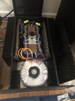
Really enjoying this now hum free amp. And the combined 408,000uF capacitance hasn't popped the slow start cct yet.
Ta to Mr Pass and ZM 🙂
A fundamental question, the original front end board had 3 stages, by my count, and the new front end board has 2 stages, the fewer the better, so what does this do to the phase of the output. Do we need to reverse the speaker cables. 🙂
I think so, what say ye?
I think so, what say ye?
I count two stages in the front end of BOTH the original Stasis and the new revised design. I'm looking at the schematics attached to post #1 of this thread.
Original: STAGE1 is 6571 diff pair ; STAGE2 is 2N4250A common emitter
New revision: STAGE1 is LSK170 diff pair ; STAGE2 is 2SA1381 common emitter
New revision: STAGE1 is LSK170 diff pair ; STAGE2 is 2SA1381 common emitter
I think we are looking at different schematics. You are looking at the Stasis 2,3 where I am looking at the second schematic, which applies to me, the SA-1 which has:
Stage1 the 2n5566 Differential pair out through the cascode Q4, to second stage Q8 on the positive side through Q10, to third stage Q17 on the positive side, which drives the output stage Stasis Voltage transistors Q19 and Q39 on the positive side to the Current Transistors Q21 - Q57.
Stage1 the 2n5566 Differential pair out through the cascode Q4, to second stage Q8 on the positive side through Q10, to third stage Q17 on the positive side, which drives the output stage Stasis Voltage transistors Q19 and Q39 on the positive side to the Current Transistors Q21 - Q57.
And I have been working on the CAD drawing for the TO3 transistor mounting plate and heat spreader bar so no drawings or pics yet, but they are coming.
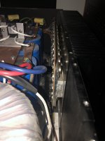
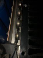
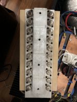
Pic of the output cans mounting plate/heatsink and heat spreader bar. Found the 1/4” thick plate is 4.5” wide.
Attachments

ok, here are the .DXF files for the transistor mounting plates one for the SA/1, SA/2, and SA Mini. as well as the heatspreader bars and a pdf file to see what they look like.
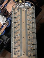
For the heatspreader bars you thread the small holes with 10-24 and the larger holes with 1/4-20. Put thermal grease between the 2" heatspreader bar and the transistor mounting plate. Put nylon spacers in the larger transistor screw holes in the transistor mounting plate. Use 1/4" long by 1/4" outer diameter, 1/8" inner diameter. Then place gasket on the transistor mount plate then PCB on top of that and put 10-24 x 1/2" screws through the PCB and transistor mount plate into the heatspreader bar, making it one assembly.
Then one at a time you can mount the transistors with thermal insulators. Check that the legs of the transistor, base and emitter do not make contact with mounting plate. Then solder the legs and mount the emitter resistors and other components.
I need to take a couple more pictures to make this clearer.
Attachments
-
Threshold SA1 heatspreader.pdf1.6 KB · Views: 196
-
Threshold SA2 heatspreader.pdf1.4 KB · Views: 162
-
Threshold SAmini heatspreader.pdf1.5 KB · Views: 181
-
Threshold SAmini Output Plate.pdf4 KB · Views: 151
-
Threshold SA1 Output Plate.pdf7.4 KB · Views: 197
-
Threshold SA2 Output Plate.pdf4.9 KB · Views: 160
-
Threshold SA1 Output Plate.zip26.9 KB · Views: 142
-
Threshold SA2 Output Plate.zip4.4 KB · Views: 134
-
Threshold SAmini Output Plate2.zip24.5 KB · Views: 124
-
Threshold SA1 heatspreader.zip20.4 KB · Views: 117
-
Threshold SA2 Heatspreader.zip20.5 KB · Views: 122
-
Threshold SAmini heatspreader.zip20.4 KB · Views: 179
I've skimmed through the thread. It's a lot to digest. A few questions for the cognoscenti-
1. I can use the FE cards, either Papa's or Zen Mod's as a front end for old Hafler Amps, correct?
2. Has anyone used a FE with a Hafler amp? Any values I should adjust for using the FE with a Hafler?
3. I believe Haflers use Lateral mosfets as output devices. Using my so-so transmutation powers, can you build as Stasis OS using laterals? All Stasis are BJT based, correct?
1. yes; even if I (still) didn't tried, no reason to doubt functionality; I believe that I posted schm somewhere .... observe that NFB takeout point is best to move to OS output
if you can't find my schm for that, just buzz
2. above
3. most likely you can, if you have strong reason; all Treshold amps were bjt OS, as far as I know
if you can't find my schm for that, just buzz
2. above
3. most likely you can, if you have strong reason; all Treshold amps were bjt OS, as far as I know
Thanks, ZM and Von Ah.1. yes; even if I (still) didn't tried, no reason to doubt functionality; I believe that I posted schm somewhere .... observe that NFB takeout point is best to move to OS output
if you can't find my schm for that, just buzz
2. above
3. most likely you can, if you have strong reason; all Treshold amps were bjt OS, as far as I know
Yes, the Stasis/Hafler schematic you posted is posting #670 as Von Ah noted.
Looking at the schematic for the ZM Stasis FE and the ZM Stasis/Hafler FE, the difference seems to be showing the FE board connection to the Hafler N/P devices. Which is helpful, just wanting to note that I don't see any part or value changes to the ZM FE board itself.
I have a non-working DH220 which should be a good starting point. I'll open it up and see how I can fit the new boards.
For the lateral OS question- I have some 2SK1058/2SJ162 in the parts drawer. Just wondering if I built a new OS if I needed to buy BJT or if I could use the SK/SJ parts. Good to know that it "should" work.
- Home
- Amplifiers
- Pass Labs
- New Stasis front end