125mVpp ripple in the PSU rail is a lot - but about par for the course with a regular CRC. I don’t expect the buzz to be that loud. What is the ripple at speaker output? You might have a ground loop? Is the buzz still there when the inputs are shorted to ground?
A cap Mx based PSU can bring that ripple in the PSU down to a few mV rms and should substantially make it quieter if the buzz is coming from the PSU and the amp has low PSRR.
A cap Mx based PSU can bring that ripple in the PSU down to a few mV rms and should substantially make it quieter if the buzz is coming from the PSU and the amp has low PSRR.
Well, well...I think I know a little more, and it is very strange...
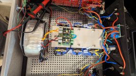
Single transformer, two PSU boards, one for each channel. Using two of these:

I did as ZM suggested and wound the Iq to half the value and noticed this had no impact on the ripple's amplitude or frequency. Hmmm. So, I detached the the amp board from the PSU, and no impact on the ripple, still the same. Checked the other rail, +ive, on the PSU of the same channel, no ripple. Re-attached the amp boards and no ripple on the +ive rail, but still the same ripple on the -ive rail. Conclusion...it's the PSU boards. Something strange is going on.
For giggles I checked the other channel PSU and that has the same ripple on both rails (100mV+). Detaching the amp boards doesn't change the ripple's amplitude or frequency.
So either, I built one channel's rail right, the one with no ripple and three other rails wrong, all with ripple.
Shheezz...
I feel like breaking out a conventional PSU with a bridge rectifier and a couple of big, coffee mug sized, caps 🙂
Single transformer, two PSU boards, one for each channel. Using two of these:
I did as ZM suggested and wound the Iq to half the value and noticed this had no impact on the ripple's amplitude or frequency. Hmmm. So, I detached the the amp board from the PSU, and no impact on the ripple, still the same. Checked the other rail, +ive, on the PSU of the same channel, no ripple. Re-attached the amp boards and no ripple on the +ive rail, but still the same ripple on the -ive rail. Conclusion...it's the PSU boards. Something strange is going on.
For giggles I checked the other channel PSU and that has the same ripple on both rails (100mV+). Detaching the amp boards doesn't change the ripple's amplitude or frequency.
So either, I built one channel's rail right, the one with no ripple and three other rails wrong, all with ripple.
Shheezz...
I feel like breaking out a conventional PSU with a bridge rectifier and a couple of big, coffee mug sized, caps 🙂


Sometimes one can know too much and not be able to deduce anything logical...
The PSU boards in the amp are stacked. Most of the testing has been done on the top board, I thought it time to do a bit of isolation and work on the bottom board and build from there...
I checked for any continuity between the two stacked boards through the metal pillars between the two. There wasn't any.
With no load on the PSU the bottom board output looks like this:

The noise spike is always there.
This is different from what I measured with the top board in place...hmmm.
Rails are +/-35V.
Iq 70mA per device, about 0.45A per rail.

Iq 100mA per device, about 0.6A per rail.

Iq 150mA per device, 0.9A per rail.

All increasing in size as the Iq increases, pointing to ZM's conclusion that there just ain't enough capacitance in them there rails, about 44kuF per rail. But, at 0.5A per rail with about 50mV of ripple seems very poor performance,
I also noticed, no idea whether it is a red-herring, but the ripple trace was moving up and down as a whole, as if there were another, lower frequency signal. I tried to capture this by increasing the time base to 100ms and there does appear to be something else in there:


You can see it here as the ripple trace follows a definite curve.

The yellow trace is the speaker output with the input shorted. And yes, you can't see the ripple, but I can hear it on the speakers - illogical and just plain wrong.
Next to try is a couple of resistors on the ends of the PSU boards to simulate load to confirm that the ripple is all in the boards.
I have a F5T hanging around, I could transplant the DIYAudio PSU from that to this Stasis amp, thinking...
The PSU boards in the amp are stacked. Most of the testing has been done on the top board, I thought it time to do a bit of isolation and work on the bottom board and build from there...
I checked for any continuity between the two stacked boards through the metal pillars between the two. There wasn't any.
With no load on the PSU the bottom board output looks like this:
The noise spike is always there.
This is different from what I measured with the top board in place...hmmm.
Rails are +/-35V.
Iq 70mA per device, about 0.45A per rail.
Iq 100mA per device, about 0.6A per rail.
Iq 150mA per device, 0.9A per rail.
All increasing in size as the Iq increases, pointing to ZM's conclusion that there just ain't enough capacitance in them there rails, about 44kuF per rail. But, at 0.5A per rail with about 50mV of ripple seems very poor performance,
I also noticed, no idea whether it is a red-herring, but the ripple trace was moving up and down as a whole, as if there were another, lower frequency signal. I tried to capture this by increasing the time base to 100ms and there does appear to be something else in there:
You can see it here as the ripple trace follows a definite curve.
The yellow trace is the speaker output with the input shorted. And yes, you can't see the ripple, but I can hear it on the speakers - illogical and just plain wrong.
Next to try is a couple of resistors on the ends of the PSU boards to simulate load to confirm that the ripple is all in the boards.
I have a F5T hanging around, I could transplant the DIYAudio PSU from that to this Stasis amp, thinking...
Last edited:
125mVpp ripple in the PSU rail is a lot - but about par for the course with a regular CRC. I don’t expect the buzz to be that loud. What is the ripple at speaker output? You might have a ground loop? Is the buzz still there when the inputs are shorted to ground?
A cap Mx based PSU can bring that ripple in the PSU down to a few mV rms and should substantially make it quieter if the buzz is coming from the PSU and the amp has low PSRR.
Strangely I'm not "seeing" the buzz on the outputs until the amp is warmed through after about an hour or so.
I've been really careful with the grounding. And yes the buzz is still there when the inputs are shorted.
The CapMX I did try, and this is something that pointed me at a grounding problem or lack of capacitance; the CapMXs buzzed too, though they only had 10kuF on each rail for each channel.
With an active bridge, you cannot use center tapped transformers with a common tap to ground to make dual rail. Each active bridge needs to get isolated AC secondary.
If one of the MOSFETs has gone bad, you are not getting full wave rectification, hence higher ripple. It will almost work except that the ripple is higher.
Maybe try a standard silicon bridge and caps and see if that helps.
Those loads are relatively low and I am suspecting you have a damaged LT4320 or rectifier MOSFET.
With an active bridge, you cannot use center tapped transformers with a common tap to ground to make dual rail. Each active bridge needs to get isolated AC secondary.
If one of the MOSFETs has gone bad, you are not getting full wave rectification, hence higher ripple. It will almost work except that the ripple is higher.
Maybe try a standard silicon bridge and caps and see if that helps.
Those loads are relatively low and I am suspecting you have a damaged LT4320 or rectifier MOSFET.
Yeah rectifier has its own isolated secondary winding.
If a MOSFET was bad or the LT4320 was bad, would the problem, ripple, only be seen on load and not off load?
I am going to try a more traditional approach for the PSU to confirm whether there lies the problem.
Third time lucky on the PSU...
 2021-11-28_11-19-09 by Garf Arf, on Flickr
6x68,000uF caps, 2x0.22R in parallel between each cap bank. 22kR bleed resistors.
Earthing is now starred at the end on the PSU, though Input signal grounds still go to the FEs.
Just biasing the boards.
2021-11-28_11-19-09 by Garf Arf, on Flickr6x68,000uF caps, 2x0.22R in parallel between each cap bank. 22kR bleed resistors.
Earthing is now starred at the end on the PSU, though Input signal grounds still go to the FEs.
Just biasing the boards.
Attachments
Last edited:
And I can confirm, no hum is heard at the speakers even with each device biased to 200mA on both channels.
Just to get a bit of time this week to sit down and have a good listen.
Capacitance FTW.
Just to get a bit of time this week to sit down and have a good listen.
Capacitance FTW.
In 1987 I bought a pair of Threshold SA/1s, enjoyed them for a few years before I had to sell them because of a divorce, kept the house. A couple years later I made some duplicates from the info I took off the Amps and the repair schematic.
A few years ago, I rebuilt them using bigger heatsinks, going from a 1 KVA to a 2400 KVA toroid, from 2 60k uf to 8 79k uf Caps with a pair of big inductors between each bank of 4, a 10 uf and .1 uf Film cap across the end of the power supply rails, and a new soft start. I kept the front end and output boards the same. This made for a very stiff unregulated power supply at +/- 45v per rail, and I was able to boost the bias to twice of what it was, and it sounds sweet and runs at 50C.
Back then I had to hand etch my own PCBs. Since then, I have created many Output boards for amps with a PCB CAD package. The SA/1 had 20 TO3 devices on each board, for a total of 40 output devices, on a 15 1/2" long PCB x 6" high.
The PCBs were scewed to a ¼” x 6” x 15 ½” plate of aluminum and the devices were placed on the plate with Mica and grease so the transistor, screws and transistor legs were isolated from the plate through holes in the plate and into the PCB.
Then a ½” x 3” x 15 ½” bar is screwed to the ¼” plate down the center with grease between them. The 3” bar is then screwed to the heatsinks. This gives you great thermal mass. You can see Pics in a few places on the forum.
So, I was wondering if there was interest in a PCB for the TO3 cans to do it right. The TO-220 are much easier and cheaper to work with but I still like the TO3s. I can create the gerbers and post. It is a lot of work but if there is interest, I am happy to do it.
Definintely, I mentioned this somewhere at the beginning of this thread, but sadly I do not have the skills to desing TO3 boards.
I have several trays of TO3's
I have several trays of TO3's
Since the TO3 case is a standard layout it can be used with any if the pinout is the same, Collect on the case, base and emitter on the legs. I used the original MJ15022 and MJ15023. They are still available from Mouser. $7-8 each. Back then they were $2 each in 100 lots.
Thanks, I would be interested with a board with say 8 or so TO3 devices - don't need 20 per channel.
Since the heatsinks come in 4 and 8 inches widths with the 3" long fins, HeatsinkUSA.com,
How about 3 boards, one each for 10, 14 and 20, in 7 1/2", 11 1/2", and 15 1/2" long respectively, for 2, 3 and 4 heatsinks. You need 2 devices as the stasis voltage drivers and then 8, 12 and 18 current devices. And you don't have to stuff all the locations if you don't want as many.
How about 3 boards, one each for 10, 14 and 20, in 7 1/2", 11 1/2", and 15 1/2" long respectively, for 2, 3 and 4 heatsinks. You need 2 devices as the stasis voltage drivers and then 8, 12 and 18 current devices. And you don't have to stuff all the locations if you don't want as many.
I have actually always wondered if someone knew where to source exact replacement heatsinks for the stasis series of threshold amps. I really like their profile. I haven't been able to find them though. I know ATI1502 has similar but deeper heatsinks, forte and Nakamichi has similar heatsinks as well in their older amps.
for the heatsink, these are the closest I have found to the original.
3.945" - HeatsinkUSA
but I also really like these"
8.000" Serrated Fin - HeatsinkUSA
3.945" - HeatsinkUSA
but I also really like these"
8.000" Serrated Fin - HeatsinkUSA
- Home
- Amplifiers
- Pass Labs
- New Stasis front end