TO3 outputs....... :
1. if you really have bunch of good ones
2. if you really like them
3. if you already have ready heatsinking arrangement for them
4. if you really like them
if you don't have ticked all 4 ........ why bother
1. if you really have bunch of good ones
2. if you really like them
3. if you already have ready heatsinking arrangement for them
4. if you really like them
if you don't have ticked all 4 ........ why bother
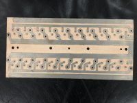
I dug out my one extra original board that was hand made. The board is single sided and few holes, some for mounting and the transistor holes. The there is no solder mask and the emitter resistors were soldered to the surface, as was the wiring. The smaller heat spreader bar is only 2” wide not 3”. I will open my amp soon and give you a better picture of how it was made. Also the original amp did NOT base resistors and was never prone to oscillation like a MOSFET might be. And now that I have been able to measure the PCB I find that 10 devices would make the board 7” long, 14 - 9 1/2”, and 20 devices 13 1/2” long
Attachments
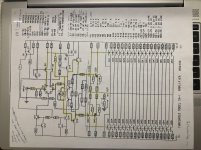
The Schematic is in the original first post by Nelson Pass, Top Row Right most pic. And here is the Original schematic of the SA/1 from my repair archives.
Thanks again for the info, look forward to where you go with this. Are you planning a GB or just going to publish Gerbers for members to follow up with?
We certainly weren't afraid to parallel a few transistors back then.

What is the most you ever paralleled (any pix)?
I am just planning to layout the board and publish Gerbers. At this point I am not touching my amps so I don't need any boards, except to open one and take pictures and clean out the cat hair, he likes to sleep on top of the amps when they have just been turned off.
I don't think many people are into the TO3 Cans. People can lay the circuit board on top of the 1/4" Aluminum plate and mark the places to drill and tap. It is a bit more work to build with TO3s and for most people, as ZenMod says, Why bother, but for the brave I will layout boards.
I don't think many people are into the TO3 Cans. People can lay the circuit board on top of the 1/4" Aluminum plate and mark the places to drill and tap. It is a bit more work to build with TO3s and for most people, as ZenMod says, Why bother, but for the brave I will layout boards.
Ok, I have gerbers. Remember it is the back side of the PCB that you see, the front side is face down against the 1/4" aluminum plate. Unfortunately the holes are probably plated through and have pads on the front so you will need a thin non-conductive gasket between the PCB and the aluminum plate. Also, the screws through the TO3 can go through the plate but cannot touch it. I checked mine with an ohmmeter to be sure no shorts. I should have drilled the plate holes for the screws large enough for a nylon spacer around the screws. And I will work on a .dxf file for drilling the plates. And pics of the assembly to show how it is done.
Attachments
-
Threshold SAmini 10D_gerber.zip11.3 KB · Views: 153
-
Threshold SA2 14D_gerber.zip13.6 KB · Views: 129
-
Threshold SA1 20D_gerber.zip17.7 KB · Views: 135
-
Threshold SAmini 10D backside.pdf35.7 KB · Views: 171
-
Threshold SAmini 10D Topside.pdf39.8 KB · Views: 184
-
Threshold SA2 10D backside.pdf49.4 KB · Views: 172
-
Threshold SA2 10D Topside.pdf54.6 KB · Views: 191
-
Threshold SA1 20D backside.pdf68.6 KB · Views: 177
-
Threshold SA1 20D Topside.pdf77.3 KB · Views: 225
The Emitter resistors, as I mentioned earlier are mounted to the surface of the PCB traces, the Pic will explain it better. I used 1 ohm wirewound non-inductive resistors.
If you look at the PCB, the top and bottom wide traces don't connect to anything. That is where you solder a wire to end of the voltage rails, the emitter resistors leads are formed to reach the transistor emitter and across to the voltage rail trace. It is the voltage across the resistor that you measure to set the initial bias, the tune up to 50 C. Wait for the picture, you will see. Hopefully I can post pics tomorrow.
- Home
- Amplifiers
- Pass Labs
- New Stasis front end