Ah...get ya...do you have proper big caps after Cap Multi?
that I'm sayin'
🙂
And no, just wires *sadness*. The cap MX is a diyaudio design by Mark Johnson from the latter part of this thread Juma's Easy-Peasy Capacitance Multiplier
I assume my scope would see that meeeeeeew sound?
well, anyone is having an opinion, so why should I be the last ..... one 
see by our self - listen some time like you made it
add later, say, 20-ish or more mF per rail, after Cap M. , and listen
choose what you like more
see by our self - listen some time like you made it
add later, say, 20-ish or more mF per rail, after Cap M. , and listen
choose what you like more
Could be my measuring technique, but I do appear to be getting about a 150mV, 25Mhz signal superimposed on the supply rails, with a strange "buzzing", low level, through the speakers.
So, I'm going to try a more conventional PSU, CRC and bridge rectifiers.
So, I'm going to try a more conventional PSU, CRC and bridge rectifiers.
Yep, buzzing all the time, not loud, not 50Hz mains (not a hummmm...I'm naming tunes tonight!). It isn't right. It is on both channels, same level, same form.
I tried redressing a couple of mains/transformer cables, but to no avail. The signal wasn't on the input to the Cap MX after the diodes.
I've not pushed a sine wave or squarish one in as yet, ran out of time this evening. I'll try again tomorrow. Would I be best taking the FE boards off the OS and testing them separately?
disconnect one channel entirely from Donut, so no surprises while your attention is on other one
feed it with some signal - sine , without load and observe
connect dummy load, observe
feed with some square signal, compare input and output (just to be sure that input is proper square, observe output
write here; square will tell is it your amp on verge of oscillation
if you have Peasant style PSU&filter, try with that, observe is there any difference
Thank you ZM. I shall investigate over the weekend and report back. Just too much work during the week 🙁
A little latter than I wanted, but work got in the way, and Windows...
My little sig gen died. I had to use various signal generator apps in Windows to generate various test tones and for some reason I couldn't get a decent square wave at all...very strange...
Anyway, I replaced the Cap MX with something more "peasant" like and it looks like both the audible noise and strange 'scope readings have gone. I've only managed to test the amp on a sine wave, but it looks good.
New PSU

@3kHz 2.5V in

@1.1kHz 2.5V in

@19.9kHz 2.5v in

A square wave, hmmm! @3kHz 2v in

Both channels measured the same. Rail voltages are +/-35VDC.
I have bought a simple sig-gen so I will retest with something a little more square once it arrives.
I've biased both sides to about 215mV over the emitter resistors and there is still a very faint, "get your ear right against the speaker to hear it" buzz...
My little sig gen died. I had to use various signal generator apps in Windows to generate various test tones and for some reason I couldn't get a decent square wave at all...very strange...
Anyway, I replaced the Cap MX with something more "peasant" like and it looks like both the audible noise and strange 'scope readings have gone. I've only managed to test the amp on a sine wave, but it looks good.
New PSU
@3kHz 2.5V in
@1.1kHz 2.5V in
@19.9kHz 2.5v in
A square wave, hmmm! @3kHz 2v in
Both channels measured the same. Rail voltages are +/-35VDC.
I have bought a simple sig-gen so I will retest with something a little more square once it arrives.
I've biased both sides to about 215mV over the emitter resistors and there is still a very faint, "get your ear right against the speaker to hear it" buzz...
Last edited:
I've told ya that amp needs some proper Reservoir Cojones, and that Cap Multi (well done) can do filtering duty, but is not having energy storrage
same as thhat you're using physical choke as series element, but as last element in chain - no go
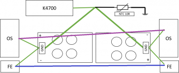
regarding slight buzz - you're having dedicated PSUs for each channel, but common xformer; you need to address GND wiring with utter care
try fat wire bridge between main GND points of two channels pcbs
if that cures it - either leave it, or try other way of killing it
buzz, not the amp 🙂
is that thing singing, or just being happy measured?
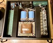
edit: one thing more - that Donut really belongs to other side of box, far as possible from inputs and FE pcbs
same as thhat you're using physical choke as series element, but as last element in chain - no go
regarding slight buzz - you're having dedicated PSUs for each channel, but common xformer; you need to address GND wiring with utter care
try fat wire bridge between main GND points of two channels pcbs
if that cures it - either leave it, or try other way of killing it
buzz, not the amp 🙂
is that thing singing, or just being happy measured?
edit: one thing more - that Donut really belongs to other side of box, far as possible from inputs and FE pcbs
Last edited:
ZM, thank you for the pointers on the PSU 🙂 First time with a CapMX and I learnt something, which is always good.
Earthing looks like this atm

Earths from the OS and the FE to the GND on the PSU boards are about 10A capacity. The wire from the PSU GNDs to the rear star are 13A capacity. All taken from three core mains wire.
And yes, I should have the boards the other way around. When the Cap-MX boards were there there wasn't the space, but maybe now....🙂
Thanks again for all your help and support ZM...and NP for the amp.
ps. I did have a quick listen last night and I found it a very clear amp, good separation of individual sounds and instruments...I need to listen more to get the gauge of the amp yet...
Earthing looks like this atm
Earths from the OS and the FE to the GND on the PSU boards are about 10A capacity. The wire from the PSU GNDs to the rear star are 13A capacity. All taken from three core mains wire.
And yes, I should have the boards the other way around. When the Cap-MX boards were there there wasn't the space, but maybe now....🙂
Thanks again for all your help and support ZM...and NP for the amp.
ps. I did have a quick listen last night and I found it a very clear amp, good separation of individual sounds and instruments...I need to listen more to get the gauge of the amp yet...
why "NP"?
I did all the Work, he just gave schematics.....
besides - he's gone to Ibiza again, so left me here to wrestle with Greedy Boyz

listen more and inform us , about rest of details
ya know, system synergy and all fancy words 🙂
I did all the Work, he just gave schematics.....
besides - he's gone to Ibiza again, so left me here to wrestle with Greedy Boyz
listen more and inform us , about rest of details
ya know, system synergy and all fancy words 🙂
btw
this FE will transform any of your old Hafler in proper beast
realized that realizing that I have cleaned (inside) Hitachi HMA-6500, as possible radio/tv/summer amp for living room, waiting for resurection .......
I have the very same amplifier that I want to transform.
Simplest option is to go for what ZM said. Just 1 pair of Hitachi Laterals per side. Would this use the schematic from #670?
New Stasis front end
Other Frankenstasis idea (half-baked) is to use the outputs and heatsinks from this PA amp I have: Ashly FET-2000M. 4 pairs of TO3 laterals per side. This would include fan cooling.
Am I better off waiting for the presumed FET stasis OS?
I know this is a little off topic, so if I move forward, I’ll start a new thread.
Attachments
Last edited:
yup, that's idea of Hitachi amp OS fed with Stasis FE
if you end as happy with small one, redo bigger one too
disclaimer - I didn't tried it, yet, but I see no reason to not work good
if you end as happy with small one, redo bigger one too
disclaimer - I didn't tried it, yet, but I see no reason to not work good

.......
ps. I did have a quick listen last night and I found it a very clear amp, good separation of individual sounds and instruments...I need to listen more to get the gauge of the amp yet...
did ya ..... more ?
Sadly, work got in the way, and still is...did ya ..... more ?
I'm going to rebuild the amp this weekend, fingers crossed.
There's some interesting discussion about base resistors for the power transistors over at the Power amp OUTPUT STAGE measurements shootout.
My sim gives Rb = 22R -> THD = 0.831556%, and Rb = 2.2R -> THD: 0.692364%, OS only.
My sim gives Rb = 22R -> THD = 0.831556%, and Rb = 2.2R -> THD: 0.692364%, OS only.
what's decimal point, between friends? 
last thing I was taking care of was value of base resistors ...... just put whatever you want
mine was to make pcbs by Papa schmtcs ........ in fact, in original OS schematics (first page) there wasn't base resistors at all - I did drew them as optional
so, same as type of OS transistors, choose preferred value of base resistors, if any
- Home
- Amplifiers
- Pass Labs
- New Stasis front end