In stock,and affordable - a lot less expensive than Cree's inital offering, but then, there's competition out there now.
Some practical testing
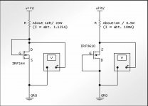
I bought some of the C2m1000170d and just did a quick and cheerful VGS matching exercise on them. Results below. Current and V(supply) are derived values. Setup attached. V(res) is the voltage over the resistor in the test and is used to derive the current.
# VGS Vres I(calc'd) V(supply)
1 8.21 13.40 0.84 21.61
2 8.13 13.50 0.84 21.63
3 8.16 13.44 0.84 21.60
4 8.08 13.42 0.84 21.50
5 8.06 13.38 0.84 21.44
6 8.26 13.26 0.83 21.52
7 7.91 13.55 0.85 21.46
8 8.10 13.55 0.85 21.65
9 8.06 12.62 0.79 20.68
10 7.90 13.75 0.86 21.65
11 8.21 13.55 0.85 21.76
12 8.13 13.60 0.85 21.73
13 8.12 13.62 0.85 21.74
14 8.19 13.46 0.84 21.65
15 8.10 13.58 0.85 21.68
16 8.07 13.57 0.85 21.64
Attachments
Last edited:
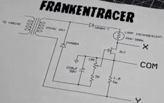
Is there interest in me trying to curve trace them? I haven't a curve tracer, but I've been looking at This and I could bodgy something similar up easily enough...
Aspringv..
I for one would be very interested in seeing the curves, especially in the region we are accustomed to working in. I have an old Heathkit curve tracer I built in 1974 that I planned to use when I could get some of these devices in hand. Have not gotten that far yet though. I hope you have a chance to build your test setup. Thanks for the matching information. Very interesting test data. Did you use heat sinking during the tests?
I certainly did mikegranger. Although I wouldnt put too much stock in the numbers I got as I tried to be quick to prevent heating up of the get. So the numbers are the first numbers off the multimeter after I powered up the test rig.
I'll get on that curve tracer rig today I hope!
I'll get on that curve tracer rig today I hope!
I recently had the opportunity to witness one of Transphorm's GAN JFET
over silicon MOSFET cascodes explode across the room. This was on one
of OnSemi's evaluation modules. I guess they are calling Transphorm's
devices their own. Didn't bother to cover or erase the original markings.
From the leftover chunks, its pretty obvious the GAN and Silicon were
two separate entities molded into one package... Or maybe that was a
silicon Schottky across the lower device. All I can say, was two square
impressions where things used to be.
I certainly did mikegranger. Although I wouldnt put too much stock in the numbers I got as I tried to be quick to prevent heating up of the get. So the numbers are the first numbers off the multimeter after I powered up the test rig.
I'll get on that curve tracer rig today I hope!
Presumably you are modifying the Frankenstein to suit the enhancement mode n channel cree ? The original was designed for negative bias voltages.
Michel Rothandher has posted a Youtube vidio showing how to build a
verry simple curve tracer for your osiliscope.
https://www.youtube.com/user/mikerothacheraudio
verry simple curve tracer for your osiliscope.
https://www.youtube.com/user/mikerothacheraudio
Attachments
Presumably you are modifying the Frankenstein to suit the enhancement mode n channel cree ? The original was designed for negative bias voltages.
I believe if you reverse the diode that powers the variable bias circuit and the 220 microfarad capacitor that smooths the the bias voltage, the bias will be the correct polarity for enhancement devices.
Maybe Michael R will clarify this.
Hi everyone,
These are not power jfets, but they are said to be ultra low noise.
I think they can only handle 20v.
Scroll to the bottom of the site page.
CRYSTALONICS | semiconductor manufacturer of Small Signal Transistors, JFETS, DUAL TRANSISTORS, QUAD TRANSISTORS, POWER TRANSISTORS, CURRENT REGULATOR DIODES, VARACTOR DIODES and custom HYBRID MICROCIRCUITS
Vince
Sorry folks - I have parts and I've knocked up a curve tracing rig, but I've been travelling for work a bit recently. I'll get curves up when I get some me time.
I think I fall in love for this device:
C2M0280120D Cree, Inc. | Mouser
However it is the case to test it before.
The datasheet of these components are quite strange: for a 1200 volts (or more) devices, paradoxically, they are shown output curves up to 10 V ????? ......
Also another oddity: they are declared a voltage treshold of 2.8V max but the curves depart from a minimum of 10 V of Vgs. So it seems that companies do their best to be less readable these datasheeet, lately. They think only about switching......
A sample must be tested in a short time!!! 😉
Attachments


aspringv,Sorry folks - I have parts and I've knocked up a curve tracing rig, but I've been travelling for work a bit recently. I'll get curves up when I get some me time.
Anything new to tell us ? I have not had the chance to do anything more yet. Just wondering.......
I've been somewhat snowed under with work recently so its been on the back burner for a while. However, I hope to get a chance to do some testing on Sunday should the stars align!
Progress
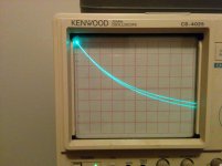
Curve tracer up and running - took a while due to drama with the bulb I used.
I'll pop one of the SIC FET's on after dinner.
Curve tracer up and running - took a while due to drama with the bulb I used.
I'll pop one of the SIC FET's on after dinner.
measurements
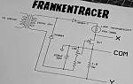
Here you go. Some small changes from the original frankentracer rig. The 1R resistor is actually about 0R94, and the lamp was swapped for 21R4. The bias circuit was altered to give a positive voltage to the gate.
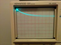
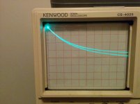
X axis is .5V a division, Y axis is .2V a division. Bias at 6V, 7V, 8V, and 9V as you go.
It's all a learning experience for me, so please if you'd like different measurements please ask. I've no idea why the graph is inverted either 🙂
Here you go. Some small changes from the original frankentracer rig. The 1R resistor is actually about 0R94, and the lamp was swapped for 21R4. The bias circuit was altered to give a positive voltage to the gate.
X axis is .5V a division, Y axis is .2V a division. Bias at 6V, 7V, 8V, and 9V as you go.
It's all a learning experience for me, so please if you'd like different measurements please ask. I've no idea why the graph is inverted either 🙂
Attachments

Hi aspringv,
Nice work!
Thanks for taking the time and doing the work so we can all see the curves for these interesting devices. I appreciate it very much.
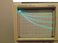
I took the liberty to stitch your four curve photos into a composite image so I could get a better feel for the characteristics. attached is the composite for all to see. It looks promising to my untrained eye.
Nice work!
Thanks for taking the time and doing the work so we can all see the curves for these interesting devices. I appreciate it very much.
I took the liberty to stitch your four curve photos into a composite image so I could get a better feel for the characteristics. attached is the composite for all to see. It looks promising to my untrained eye.
Attachments
- Home
- Amplifiers
- Pass Labs
- new SiC JFETs?