That C2m1000170d has a max power disipation 0f 69W as oposed to the 36W of the IRF610 and it comes in the larger to-247 package which will have a lot lower thermal
resistance from the package to the heatsink than the to-220 case the IRF610 has. And to
my untrained eye it looks like the curves for this bad boy are a lot closer to a triode than
most mosfets.
resistance from the package to the heatsink than the to-220 case the IRF610 has. And to
my untrained eye it looks like the curves for this bad boy are a lot closer to a triode than
most mosfets.
I've been thinking of using some Cree SiC mosfets in a tube emulation project with transformer coupled output. A high power push-pull design might be interesting. A single ended design similar to the "Das Ist Aber Schade" project would be fairly easy and possibly quite rewarding. The original circuit using 800V ST mosfets (an Electronic Goldmine score) acquitted itself well on the bench, though it never got built up all the way with case, etc. That amp is sitting in the basement shy an output transformer (stolen for the SiCPuppy).
One thing I'll do before I post new designs is juggle transformer ratio vs power dissipation for a given B+ voltage to find the right transformer to optimize output power.
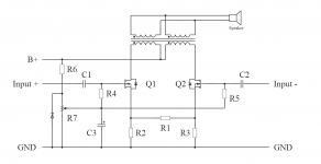
You may want to take a look at the "Terrible Twins" project which I published in Linear Audio vol 4. Back then, Jan Didden mentioned I might publish the schematics etc further, after a year or so has passed, so I think I may do that now but I will ask him first.
In this amplifier I did use Silicon MOSFETs, but have since then moved to SiC JFETs. I used Semisouth 120R100 for a couple years, at 100mA DC bias per leg in a push pull configuration, and this amplifier sounds mighty fine. Couple days ago I switched to Infineon SiC JFETs, very similar sound but I have the impression that the highs are slightly damped, and the Infineon device has double the input capacitance compared to the SemiSouth. Which makes the USC device quite attractive.....
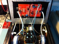
Here a sneak preview of the schematic, and a picture of the amplifier. I used regular, off-the-shelf trannies for the outputs (2x115V in, 2x12V out - originally intended for halogen lamps, -3dB point >70kHz (!))
Attachments
Hey all, anyone got a SPICE model of the C2m1000170d? I've requested one but as an amateur I'm not sure if I hit their threshold for 'authorised'. I'd like to sim an F6 with this part and see how it looks...
Thanks!
Hello, you can please find CREE MOSFET models at attachment. I am not SPICE expert, but I hope it can be useful. I look forward to your results. Have a nice day.
Attachments
How about this one?
http://www.farnell.com/datasheets/1747017.pdf
It's slightly more expensive, but it's got a power dissipation that equals the IRF240 and still a Reverse Transfer Capacitance of only 4 pF...
http://www.farnell.com/datasheets/1747017.pdf
It's slightly more expensive, but it's got a power dissipation that equals the IRF240 and still a Reverse Transfer Capacitance of only 4 pF...
Member
Joined 2009
Paid Member
What I find with most data sheets for SiC FETs - you need to keep a fair bit of voltage across Source - Drain to avoid sudden increases in capacitance. It seems for the device you reference it's only ugly below 20V. Still, that suggests for SE operation you want to have an amp and a half flowing through it with 40V across it at idle for a low powered amp - not too bad.
Last edited:
How about this one?
http://www.farnell.com/datasheets/1747017.pdf
It's slightly more expensive, but it's got a power dissipation that equals the IRF240 and still a Reverse Transfer Capacitance of only 4 pF...
Not that expensive:
C2M0160120D Cree, Inc. | Mouser
I checked out Digi-Key, and they have the 1700V Cree part for a little over 5 bucks a pop. I may get a few to play with. One thing to note is the asymmetric maximum voltage ratings for the gate (similar to the USC and Semisouth SiC jfets). This is not hard to accomodate, you just have to use a back -to- back zener clamp using two different voltage zeners for gate protection. This might be the reason I toasted a Semisouth 085 jfet when developing the "SiC Puppy", as I used a highish symmetric clamp in that design.
I didn't check the junction to case thermal resistance for the 1700V part. I'm assuming it'll be pretty large, as the larger SiC devices are already challenged in this respect. This will be the limiting factor in determining how much power you can pump through the device. Seeing as we're dealing with SiC instead of silicon, I might accept a higher max junction temperature. I'm not sure I'd want to push it any higher than 120C, though, in deference to the solder joints, the packaging material, and adjacent components that may not be anywhere near as rugged. Thermal cycling may also be an issue at higher junction temperatures.
I didn't check the junction to case thermal resistance for the 1700V part. I'm assuming it'll be pretty large, as the larger SiC devices are already challenged in this respect. This will be the limiting factor in determining how much power you can pump through the device. Seeing as we're dealing with SiC instead of silicon, I might accept a higher max junction temperature. I'm not sure I'd want to push it any higher than 120C, though, in deference to the solder joints, the packaging material, and adjacent components that may not be anywhere near as rugged. Thermal cycling may also be an issue at higher junction temperatures.
Cree Simming
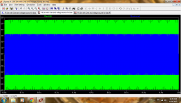
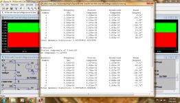
I've simmed an F6 using Cree parts vs IRF and (with the caveat that I haven't done anything other than sub parts) and the result is the IRF part swings more voltage, but there's a reduced simulated THD on the cree part. Biased to about 1.3A on the Cree and 1.5A on the IRF, for no particular reason. Sim run at 1V input at 1KHz. The value of the inductance of the simmed Jensen has a huge impact on the results, and I just plunked in an arbitrary value, so perhaps take these results with a grain of salt.
...Anyone want to help an Australian out with posting some parts? They work out to quite a lively amount to buy over here, plus postage. I have an F6 to build")
I've simmed an F6 using Cree parts vs IRF and (with the caveat that I haven't done anything other than sub parts) and the result is the IRF part swings more voltage, but there's a reduced simulated THD on the cree part. Biased to about 1.3A on the Cree and 1.5A on the IRF, for no particular reason. Sim run at 1V input at 1KHz. The value of the inductance of the simmed Jensen has a huge impact on the results, and I just plunked in an arbitrary value, so perhaps take these results with a grain of salt.
...Anyone want to help an Australian out with posting some parts? They work out to quite a lively amount to buy over here, plus postage. I have an F6 to build
Attachments
-
 Output Swing Cree 0R56 Degen vs IRF.png188.1 KB · Views: 851
 -
 Output Swing Cree 0R01 Degen vs IRF.png190.1 KB · Views: 849
 -
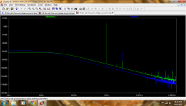 FFT F6 with Cree 0R56 degeneration.png193.3 KB · Views: 1,019
 -
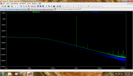 FFT F6 with Cree 0R01 degeneration.png195.1 KB · Views: 1,076
 -
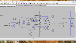 F6 Sim with Cree 0R01 degeneration.png213.4 KB · Views: 1,081
 -
F6 Sim with Cree logs with FFT and THD.zip2.6 KB · Views: 80
Last edited:
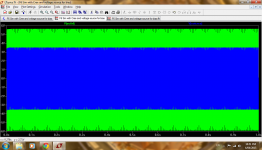
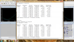
I'm just playing around with it at the moment - it's about 1am here, and I'll be away to bed shortly, so no definite results. However it looks like the Cree part sims a comparatively lower THD at lower power levels, but the situation is reversed at higher power levels.
...I just simmed again at output swing of about 14 V p to p and the simmed THD is attached.
...I just simmed again at output swing of about 14 V p to p and the simmed THD is attached.
Attachments
ZM, fair enough - I'd certainly like to build both and compare.
What I'm really trying to achieve with the sims is to narrow down the options - I've IRF parts on hand, so I could just go ahead and build and be sure of being happy in the result. But I'm always interested in trying something new and hopefully learning something new out of the process and I only have finite time to do it in, and simming is quicker than building and results in less damaged PCB's from reworking
I see your point about the cree/jensen model too - I just tried to compare two different cree parts and got the exact same result... :/ I'm not sure if that reflects the models or my lack of SPICE mojo!
New info on SiC mosfets from R-ohm .
ROHM SiC Power MOSFETs | Mouser
Have looked at one data sheet but not checked for pricing.
ROHM SiC Power MOSFETs | Mouser
Have looked at one data sheet but not checked for pricing.
- Home
- Amplifiers
- Pass Labs
- new SiC JFETs?