CFA’s don’t really slew since the output current from the DB is ~Vo/Rf rather than fixed by the LTP tail current as in a classic VFA. It is therefore better to talk about rise/fall time in a CFA. Sims show the peak output current from a CFA DB into the second stage (TIS) can be as much as 8x the standing current in response to a fast rise time input stimulus.
(Slew rate and BW are set independently of each other. You can close the loop at 1 MHz but have one smp with a 100V/us SR and another with 10V/us - only difference to do this is in the LTP degen and the tail current )
As in all these things, there is a balance to be had. PPB distortion levels and blindingly fast rise/fall times or slew rates add nothing - the fact that limited BW tube amps with 1% distortion offer much to be admired in the sound department is proof of this.
Hi Bonsai
Can I ask an unrelated question?
You recommend AFEC for CFA, does it apply to VFA as well?
Has anyone done this before?
Is the distortion improvement of AFEC for VFA equally significant?
thank you😛
Can I ask an unrelated question?
You recommend AFEC for CFA, does it apply to VFA as well?
Has anyone done this before?
Is the distortion improvement of AFEC for VFA equally significant?
thank you😛
CFA’s don’t really slew since the output current from the DB is ~Vo/Rf rather than fixed by the LTP tail current as in a classic VFA.
You can always force the amplifier to slew no matter how much mirror current you supply. But it's a non-issue if you put a filter on the input. I wrote my little essay to document my findings but I'm not claiming anything beyond the technical. I do think it's a little strange that CFAs are "allowed" to have less loop gain. It seems to be almost a religious thing. VFA design is a lot easier, too, if you run with low open-loop gain.
If CFAs sound better, maybe it's because the input stage circuits are different and/or simpler and this gives more pleasing distortion characteristics. I have no idea.
I didn't really understand CFAs until I forced myself to read some papers yesterday. There are a lot of details I still don't know, but I think I finally get the basic principles.
I agree with you, about slew rates above 1 V/uS are barely detectable and above 5 or 6 V/vS becomes acedemic (unless you are a dog or bat 🙂) and can become a futile pursuit and can have siginificant down sides like (taken from another blog and I could not have stated better myself ......there are more ) Higher numbers are not necessarily better and can lead to problems.
The buyer is going to read the spec sheet without understanding it, but will want the amp with the best numbers. I'd like to see reviews where they plot the output driving the amp with sharp square waves into a 0.1uF load capacitance. That would be "revealing."
Lm6172 is a voltage feedback op amp achieving 3000v/us...pretty low noise and fantastically stable for op-amp swap on almost any pcb...its output can swing 9v into 100 ohms load too...works up to 100 Mhz...5...40 Megohm input impedance...
Most importantly, it will run on +-5V supplies, so little danger of blowing the headphones. BTW, that chip is a CFA internally.
Edit: It also puts out up to 50mA per channel, so more than enough current to drive any conceivable headphone load.
I tried it already, i know what it can do yet there are smart circuits like Technics class aa that can make a cheap njm4556 perform simillar to tpa6120 in the audio range(except the power), so i won't trade such an expensive op' amp for its use in headphone's amplifiers other than for diy fun.Most importantly, it will run on +-5V supplies, so little danger of blowing the headphones. BTW, that chip is a CFA internally.
Edit: It also puts out up to 50mA per channel, so more than enough current to drive any conceivable headphone load.
Instead of +- 5 v rails I much preffer a7810 reg and virtual ground for any of the 99.99 dynamic headphones enjoying one single regulator noise, better cmmr and capacitor coupled output.Neve considered it , i can't really do anything better than Neve.
Nothing to do with CFA’s bring allowed to have less gain. It makes sense to describe their salient features using their ‘classic’ forms where the characteristics and benefits of each can easily be compared. There are a few designs on the forum with very high OLG ( see dadod for example) but they then also have to deal with the associated comp challenges and the differences between the two blurs. In any power amp, the ultimate limit in BW is the OPS.You can always force the amplifier to slew no matter how much mirror current you supply. But it's a non-issue if you put a filter on the input. I wrote my little essay to document my findings but I'm not claiming anything beyond the technical. I do think it's a little strange that CFAs are "allowed" to have less loop gain. It seems to be almost a religious thing. VFA design is a lot easier, too, if you run with low open-loop gain.
If CFAs sound better, maybe it's because the input stage circuits are different and/or simpler and this gives more pleasing distortion characteristics. I have no idea.
I didn't really understand CFAs until I forced myself to read some papers yesterday. There are a lot of details I still don't know, but I think I finally get the basic principles.
For practical purposes, CFA’s don’t slew. On VFA’s it’s easy enough to ensure slewing only takes place at 10x the audio band. Most VFA power amps nowadays have full power BW of 200-300 kHz, so they are not slewing below this frequency.
Last edited:
Here https://www.ovationhifidelity.com/product/model-1721/Hi Bonsai
Can I ask an unrelated question?
You recommend AFEC for CFA, does it apply to VFA as well?
Has anyone done this before?
Is the distortion improvement of AFEC for VFA equally significant?
thank you😛
The improvement is about 20 dB in distortion and about 35 dB in PSRR.
Thanks. I replaced all the missing parts on the boards with brand-new ones, and it really improved the performance. ;-)Great modifications
I just caught wind of this thread; looks like I missed a lot of fun!
I've also been very interested in the differences between VFA and CFA topologies. With the help of Jam, Mark and some others I designed a trio of front-ends for a power amp to go with my HPA-1. There was a KISS version, a VFA (based on the Hitachi architecture) and a CFA, and then two similar output stages (lateral MOSFET and vertical MOSFET). I built the KISS version first, but it sounds so good I still haven't gotten around to the other two....
I've also been very interested in the differences between VFA and CFA topologies. With the help of Jam, Mark and some others I designed a trio of front-ends for a power amp to go with my HPA-1. There was a KISS version, a VFA (based on the Hitachi architecture) and a CFA, and then two similar output stages (lateral MOSFET and vertical MOSFET). I built the KISS version first, but it sounds so good I still haven't gotten around to the other two....
I just caught wind of this thread; looks like I missed a lot of fun!
I've also been very interested in the differences between VFA and CFA topologies.
Hi, Jeff. This thread has covered a lot of ground: three projects so far. But it seems like the most traction has come from the HPA-1 clone. Thanks for publishing the schematic.
It was good that I finally sat down and figured out how CFAs work. It's a clever idea, but I can't find any objective reason to prefer CFAs over VFAs. No doubt a lot depends on the implementation and not the topology.
I'm taking a break right now, but will have some more action to report within a week and a half or so, maybe sooner.
Hi Everybody,
Please bear with me, I’m just a novice, but I’m having fun learning! I’ve been making progress on a slightly different implementation of the “A2” amp described earlier in this thread (schematic attached). One channel is built and I’m currently testing. The input ultrasonic filter and the servo output are currently disconnected for the initial testing. It’s powered by +/- 15V from a simple regulated (LM7815) supply, which is RC filtered before the IPS+VAS, rather than regulated, as the LDO regulators that Henry originally used are currently on backorder (I may see them by the end of this year!) It’s mostly looking very nice, well behaved and results are remarkably close to simulations. DC offset at the output is a measly 3 mV and seems stable, so the servo is a bit redundant, but nice to have anyway I guess. 1 kHz sine wave looks good all the way into clipping (33R resistive load).
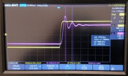
I do, however, have an issue with the square wave response that I’d be very grateful for some feedback on from the experts. A 1 kHz square wave (2 Vpp) with either no load (well 1M + 18p from the scope) or a 33R resistive load shows significant ringing at ~2.2 MHz (~ the open-loop UGF for this amp). This is worse (higher amplitude) unloaded than with the 33R load. With an external RC low-pass filter at the input (~400 kHz) the ringing is obviously cut off, but there’s still some evidence of it at the edge of the square wave, which doesn’t look very nice. Funnily enough I didn’t simulate (not sure why!) the circuit without the input ultrasonic filter prior to building, but now that I do it’s clear that the simulation predicts all of this behaviour pretty accurately - oops! The difference being that the ringing is a little higher in amplitude and decays over a slightly longer period in reality compared to simulation.
I understand that TPC does bring with it the disadvantage of high-frequency peaking in the closed-loop frequency response and some corresponding overshoot on square waves, but what I’m seeing seems more significant than this. I’d be grateful for your thoughts on whether or not I’m overly worrying and that once the final ultrasonic filter (which will be ~220 kHz with the volume pot fully open, lower frequency at lower volume) is in place the problem will all go away, or if this is something that must be tackled now. In simulation, increasing the size of the capacitor across the feedback resistor from 10p to 33p tames the ringing and leaves just a more modest overshoot. This change increases the phase margin (from 57 to 72 deg), at the expense of the gain margin (from 20 to 16 dB), but otherwise the simulations look very similar. Is there any significant downside to making this substitution? Is this the best approach to take with this problem, or would you recommend any alternatives? I’m afraid that I'm rather ignorant about TPC, but Bob Cordell’s book has been helpful and I’m making my way through Michael Kiwanuka’s paper on TPC at the moment to try to improve.
Schematic and some photos are attached. Many thanks for your thoughts.
John
Please bear with me, I’m just a novice, but I’m having fun learning! I’ve been making progress on a slightly different implementation of the “A2” amp described earlier in this thread (schematic attached). One channel is built and I’m currently testing. The input ultrasonic filter and the servo output are currently disconnected for the initial testing. It’s powered by +/- 15V from a simple regulated (LM7815) supply, which is RC filtered before the IPS+VAS, rather than regulated, as the LDO regulators that Henry originally used are currently on backorder (I may see them by the end of this year!) It’s mostly looking very nice, well behaved and results are remarkably close to simulations. DC offset at the output is a measly 3 mV and seems stable, so the servo is a bit redundant, but nice to have anyway I guess. 1 kHz sine wave looks good all the way into clipping (33R resistive load).
I do, however, have an issue with the square wave response that I’d be very grateful for some feedback on from the experts. A 1 kHz square wave (2 Vpp) with either no load (well 1M + 18p from the scope) or a 33R resistive load shows significant ringing at ~2.2 MHz (~ the open-loop UGF for this amp). This is worse (higher amplitude) unloaded than with the 33R load. With an external RC low-pass filter at the input (~400 kHz) the ringing is obviously cut off, but there’s still some evidence of it at the edge of the square wave, which doesn’t look very nice. Funnily enough I didn’t simulate (not sure why!) the circuit without the input ultrasonic filter prior to building, but now that I do it’s clear that the simulation predicts all of this behaviour pretty accurately - oops! The difference being that the ringing is a little higher in amplitude and decays over a slightly longer period in reality compared to simulation.
I understand that TPC does bring with it the disadvantage of high-frequency peaking in the closed-loop frequency response and some corresponding overshoot on square waves, but what I’m seeing seems more significant than this. I’d be grateful for your thoughts on whether or not I’m overly worrying and that once the final ultrasonic filter (which will be ~220 kHz with the volume pot fully open, lower frequency at lower volume) is in place the problem will all go away, or if this is something that must be tackled now. In simulation, increasing the size of the capacitor across the feedback resistor from 10p to 33p tames the ringing and leaves just a more modest overshoot. This change increases the phase margin (from 57 to 72 deg), at the expense of the gain margin (from 20 to 16 dB), but otherwise the simulations look very similar. Is there any significant downside to making this substitution? Is this the best approach to take with this problem, or would you recommend any alternatives? I’m afraid that I'm rather ignorant about TPC, but Bob Cordell’s book has been helpful and I’m making my way through Michael Kiwanuka’s paper on TPC at the moment to try to improve.
Schematic and some photos are attached. Many thanks for your thoughts.
John
Attachments
-
schematic_as_built_26_01_22.pdf134.3 KB · Views: 205
-
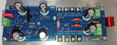 board_front.jpg296.6 KB · Views: 170
 -
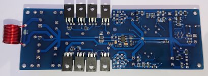 board_rear.jpg225.7 KB · Views: 168
 -
 1khz_sine_clipping.JPG320.4 KB · Views: 161
 -
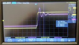 1khz_square_1M_load.JPG324.7 KB · Views: 141
 -
 1khz_square_33R_load.JPG329.1 KB · Views: 136
 -
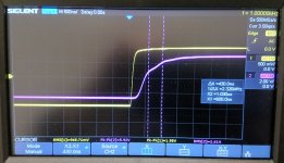 1khz_square_33R_load_400kHz_filter.JPG317.4 KB · Views: 172
First of all, congratulations on getting the circuit working. This is no small accomplishment for a project of this complexity.
In principle, the extra capacitor in the TPC network should take care of the open-loop peaking. What I've read is that the peak isn't really an issue even if you don't correct it. In any case, its frequency is around the LF cutoff of the compensation network, which is at midband and so shouldn't affect HF stability at all.
I need to go back and play with my SPICE models, because I don't believe I simulated without the input filter network, either. I need to bear that in mind for next time.
You might want to try taking your signal from before the output inductor, to make sure it's not contributing to the observed ringing. You can also try putting some capacitance on the output in parallel with the load to see if it breaks out into outright oscillation. This is a good stability torture test. The inductor does a good job of protecting the amp from destabilizing with capacitive loads, but does introduce some benign passive ringing with large cap values. I posted about this in the Bob Cordell Amplifier Book thread but don't remember if I posted about it here also.
This is likely a global loop problem because increasing the feedback lead compensation capacitor helped. Your layout is different than mine and it's no surprise you need to tweak the compensation. I may have gotten lucky with my layout. SPICE doesn't know anything about the parasitics in your particular implementation. You may need to experiment. I've been happy with the performance of my board but I should probably invest in some test gear to let me evaluate loop gain. So far, I've taken the approach that the amp seems stable so the simulation must be ok. So many factors can affect real-world behavior.
There is that RC snubber on the input to the diamond buffer. I'm a little iffy on the exact values for those parts, so some experimentation may be in order there, too.
Feel free to change the compensation values as needed to get good measured performance. As long as it's just ringing and not going nuts, I wouldn't worry too much. This is only the second reported build of this circuit, so it's really still in prototype phase, and your board is different from mine. I'd say this is very good progress.
When will you be able to give it a listen?
Here's a link to the Cordell thread where I posted my capacitive load torture test results: https://www.diyaudio.com/community/threads/bob-cordells-power-amplifier-book.171159/post-6871907
Initially, I had the ultrasonic filter in place. I repeated the tests with it disabled, and got the following square wave response with a purely resistive load:

I'm satisfied with this to the point where I don't feel like screwing with the compensation network, but I'm sure it could be improved.
Initially, I had the ultrasonic filter in place. I repeated the tests with it disabled, and got the following square wave response with a purely resistive load:
I'm satisfied with this to the point where I don't feel like screwing with the compensation network, but I'm sure it could be improved.
By the way, congratulations on the "A3" build Henry. It looks great!
Thanks, John. You've done a superb job on your amp.
Thanks for the fast reply and the encouragement! I'm also very pleased with how it's looking so far – a very promising start. I think this is testament to a solid topology that you've put together. I'd seen your discussions in the Bob Cordell thread. I'd also be happy with that level of overshoot. Clearly my parasitics are a bit more troublesome at the moment! I've not tried any capacitive loading yet. That's next on the list. What I did do is to monitor the output before the inductor and I have the same issue. In simulation the big overshoot/ringing is clear with or without the inductor too. So I don't think this is due to the inductor, that will presumably appear with a larger capacitive load. It looks like the compensation network + the transistor substitutions that I made + any parasitics in this layout. I’ll have a tweak of the compensation and see what happens then – hopefully no full-blown oscillation!
I should be able to have a listen, in mono at least, this weekend after a bit more tweaking (and some tidying up of the rather messy lash up on the bench at the moment). I’m looking forward to hearing it.
I should be able to have a listen, in mono at least, this weekend after a bit more tweaking (and some tidying up of the rather messy lash up on the bench at the moment). I’m looking forward to hearing it.
Cool. I will tell you that mono listening is a huge letdown, so don't judge by what you hear that way. You lose all the ambience and spatial cues and it just sounds really boring.
I've been busy, but when I get some time I will fire up my SPICE model and see if I can improve the compensation. I'm convinced the basic design is solid, so it should just be a matter of adjusting parts values.
I've been busy, but when I get some time I will fire up my SPICE model and see if I can improve the compensation. I'm convinced the basic design is solid, so it should just be a matter of adjusting parts values.
- Home
- Amplifiers
- Headphone Systems
- New Headphone Amplifier Design