I thought I would give a little update on this amp. It is FINALLY giving what I consider great sound. I had to do several things.
Thanks for the update. I’m just starting a ST-35 build and the information on NFB and Grounding will be very helpful.
Well done, enjoy!
I see in the mod the power supply input capacitor went from a 60uF input capacitor to a 120uF input capacitor ... and so increase the transformer heating.
If your power transformer is designed to take the extra heat no problem but if not it may well live a shorter life.
The brand new power transformers that come with the Dynakitparts.com kits are more efficient and run cooler than the one in the original ST-35. After a few hours, it's very warm to the touch, but not burning hot. The original quad cap and the one in the kit is 60-40-20uF. I restuffed an emptied out cap can with 120-120-120uF because it was a perfect fit, and I figured doubling the first cap wouldn't be a big deal with the modern power transformer. I got away with it here, but I wouldn't do it to a vintage ST-35.
Adding extra capacitance to the second capacitor after the inductor is a much safe location to increase capacitor value as it does not increase the peak rectifier current except at the point of turn on. This is also a far more effective location to reduce ripple by the addition of power supply capacitance.
I'm facing the same issue in a Chinese SEP amp kit that I am building that has a questionable power transformer. I think I'll follow your advice and not burden the transformer with the same 120-120-120uF there. I have the power supply for that amp in PSUdesigner, and I'll try some lower values for the first cap. I'm glad you brought up the issue because it had slipped my mind, and that Chinese power transformer might not like a big first cap. 👍
I wonder why Dynaco and other manufacturers always seem to put the biggest cap value first with decreasing values following?
Thanks for the update. I’m just starting a ST-35 build and the information on NFB and Grounding will be very helpful.
Feel free to message me with any questions as you go along. The MLCC caps that I used for NFB are:
https://www.mouser.com/ProductDetail/80-C317C390JCG5HA
and
https://www.mouser.com/ProductDetail/80-C330C180JHG5TA
I recommend the four grid stoppers as well. It's a very easy addition. I used these:
https://www.mouser.com/ProductDetail/71-CMF601K0000DEEB

... a SEP amp I built.
Please tell me more about this amplifier. There is remarkably little "modern" info available on Single-Ended Pentodes, and I am working on one right now. To prevent totally derailing this thread, maybe message me.
Good morning!
I have two questions. Is this terminal 3 (5 lug terminal strip) electrically connected to the chassis?
Are terminals A and B on the filter capacitor the negative poles of the capacitor? Do they form the chassis ground?
I have two questions. Is this terminal 3 (5 lug terminal strip) electrically connected to the chassis?
Are terminals A and B on the filter capacitor the negative poles of the capacitor? Do they form the chassis ground?
Attachments

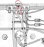
Good morning! I have another question. About the quad filter capacitor.
Since I don't have the original capacitor, I bought 4 individual capacitors (68uF 450V; 47uF 450V; 22uF 450V and 100uF), but I don't know how they connect to 1, 2, 3 and 4 and to terminals "A" and "B". Can someone help me understand these arrangements?
Bom dia! Tenho outra duvida. Sobre o capacitor quadruplo de filtro.
Como eu não tenho o capacitor original, comprei 4 capacitores individuais( 68uF 450V; 47uF 450V; 22uF 450V e 100uF), mas não sei como eles se conectam aos 1, 2, 3 e 4 e com os terminais "A" e "B". Alguém pode me ajudar a entender essas confecções?
Attachments


As i said at audiokarma.org :
The schematics is your help here.
P.12 lists the resistors and capacitors.
C8A = 60uF
C8B = 40 uF
C8C = 20 uF
C8D = 100 uF 25 Volt. This is the catode cap for the EL84
The schematics is your help here.
P.12 lists the resistors and capacitors.
C8A = 60uF
C8B = 40 uF
C8C = 20 uF
C8D = 100 uF 25 Volt. This is the catode cap for the EL84
I am continuing to assemble my ST-35 clone. The first valve is cold, there was no warming. The sound is very low, I just set up a channel. Can anyone help me?
(Estou continuando a montagem do meu clone do ST-35. a primeira válvula está fria, Não teve nenhum aquecimento. O sem está bem baixo, eu só montei um canal. Alguem pode me ajudar?)
(Estou continuando a montagem do meu clone do ST-35. a primeira válvula está fria, Não teve nenhum aquecimento. O sem está bem baixo, eu só montei um canal. Alguem pode me ajudar?)
Attachments
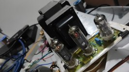
An ST35 clone uses a 7247/12DW7 first tube and EL84 power tubes. Were your PCBs designed for 6N2/6P15 and what is the schematic for your version. You know these tube are different from the “real” ST35 tubes and may not work properly unless the circuit is adapted?
If your 6N2 tube was not heated at all you probably would not hear any music. Have you accounted for the fact that the 7247 tube is a 12/6 volt tube where the 6N2 is 6V only? If you PCB was not specifically designed for 6N2 tubes you are possibly not heating it correctly. Check which 6N2 pins are connected to the 6.3 Volt heater supply and make sure pin 9 is not. Pin 9 should be grounded for 6N2.
If your 6N2 tube was not heated at all you probably would not hear any music. Have you accounted for the fact that the 7247 tube is a 12/6 volt tube where the 6N2 is 6V only? If you PCB was not specifically designed for 6N2 tubes you are possibly not heating it correctly. Check which 6N2 pins are connected to the 6.3 Volt heater supply and make sure pin 9 is not. Pin 9 should be grounded for 6N2.
Last edited:
Dear François, good morning!
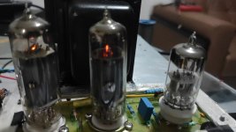
The board was designed for 7247 and 6BQ5. When I use the valves (7247 and 6BQ5) a very loud whistle comes out of the amplifier. And I have to turn it off immediately.
I will do the checks you recommended.
The board was designed for 7247 and 6BQ5. When I use the valves (7247 and 6BQ5) a very loud whistle comes out of the amplifier. And I have to turn it off immediately.
I will do the checks you recommended.
"a large whistle" could be an indication of wrong polarity of the output stage, the nfb becomes positive feedback.
To confirm this disconnect the nfb, if the amp is not "whistling" this is the cause. Switching the output from the phase spiltter to the EL84 will cure this. Or swich all plate and g2 connections between the el84.
To confirm this disconnect the nfb, if the amp is not "whistling" this is the cause. Switching the output from the phase spiltter to the EL84 will cure this. Or swich all plate and g2 connections between the el84.
What is the NFB?
How do I disconnect the NFB?
Can you explain it to me better, since I don't have much knowledge in this area?
Thanks
How do I disconnect the NFB?
Can you explain it to me better, since I don't have much knowledge in this area?
Thanks
nfb = negative feedback. Takes a signal from the speaker output ( 16 ohm tap in this case) and feeds it back to the beginning of the amp,What is the NFB?
How do I disconnect the NFB?
Can you explain it to me better, since I don't have much knowledge in this area?
Thanks
at the cathode connection of the first tube. If the phase is wrong ( transformer connection plate-g2-transformer tap )between the 2 el84 then the NFB becomes positiv creating an oscillator instead.
- Home
- Amplifiers
- Tubes / Valves
- New DynaKitParts ST-35 Build