PMA said:I know this, but simulated Aol curve, without VAS load, has F(-3dB) corner at 15kHz and at 350kHz when VAS is loaded by 22k. This is without rev. V3, and this is how it was simulated.
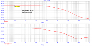
After V3, i.e. 68pF cap in buffer, simulated Aol (F-3dB) corner is at about 4kHz without VAS load and about 84kHz with VAS load.
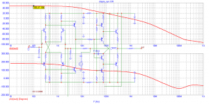
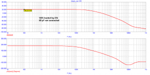
OLG plot for VAS loaded by 22k, without rev. V3:
Need to know how you determined this. If it's like in http://www.diyaudio.com/forums/showthread.php?postid=1704718#post1704718 then that is irrelevant from an open loop gain perspective. Your "open loop" # "open loop gain" required for determining the THD and output impedance.
PMA said:By disconnecting of feedback resistor and capacitor (both in simulation and measurement). Servo connected to keep output DC voltage near to zero, avoiding operating points from possible saturation.
I'm still not sure if we are talking about the same thing.
For this particular type of analysis, you can safely remove the servo from the schematics (or keep it, whatever).
Now, referring to http://www.diyaudio.com/forums/attachment.php?s=&postid=1509817&stamp=1210784770 (if that's not the real schematic, you would understand the basics anyway).
- Disconnect R38 and C13 from the output node
- Add a very large inductance (like 1GHenry) in series with R38/C13 junction to the output node.
- Connect an AC source of 1V through a very large capacitor (like 1F) to the R8/C13 junction.
- Short the input node to the ground.
- Run an AC simulation and plot the output node voltage and phase. This is the loop gain.
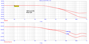
Now, repeat the above for a) circuit with VAS loaded with 22k b) circuit with 68pF compensation c) circuit with VAS loaded with 22k and with 68pF compensation.
It shouldn't take you more than ten minutes to do the above. This will certainly shed some light into what's happening. Loop gains and phase margins will then be obvious... I would do it myself, but without the component values it is unlikely to get anything helpful.
syn08 said:- Disconnect R38 and C13 from the output node
Now, repeat the above for a) circuit with VAS loaded with 22k b) circuit with 68pF compensation c) circuit with VAS loaded with 22k and with 68pF compensation.
I had disconnected R38 and C13. The result was in my previous post. It was the OPEN LOOP GAIN, with VAS load resistor as parameter. Once 22k, second curve for 10022k (like disconnected). I have also done these simulations with fixed 22k and with no VAS load. Result is the same. I have also made loop gain simulations. My computer has been full of them.
Loop gain = open loop gain x feedback divider.
The DC servo changes only very low frequencies.
Not only I have simulated the open loop gain, I have measured it in a real circuit , and the difference with simulation is about 1dB at 59dB.
I have also done everything for 22k, infinite, 68pF and 0pF. Both measured and simulated.
Once again I mention that this circuit has not a subtractor in the input, and simplifed feedback equation cannot be used.
Attachments
PMA said:Once again I mention that this circuit has not a subtractor in the input, and simplifed feedback equation cannot be used.
Well, call me stupid, but I don't know what a "input subtractor" is.
I'm not talking about any equations here (otherwise I would not mention simulations). Simulations should be "input subtractor" (whatever that is) independent and the worse I can think of is neglecting the current part in the Middlebrook model. Which can be easily fixed, in particular in the MC simulator that you are using. The complete Middlebrook method is not an approximation, but and exact method, leading to exact (simulation wise) results.
Anyways, don't bother if you don't feel like... it's just my curiosity.
I made a small mistake in the previous 4 simulations. I forgot to use the feedback capacitor. However, it is a small value (2.7pF) and affects frequency response only above 3MHz, which I hope is not the case now.
The question still remains. Reduction of distortion after the feedback is applied does not correspond the loop gain.
When VAS is loaded, distortion is decreased. Both in simulation and measurements. We measured several pieces produced, independent people, different measuring gear, same conclusion.
When VAS is loaded, distortion is decreased. Both in simulation and measurements. We measured several pieces produced, independent people, different measuring gear, same conclusion.
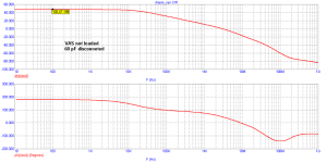
PMA said:VAS not loaded, 68 pF disconnected
(you can see that it exactly fits to what I have written)
Ok, now it starts to make some sense.
1. For no 22k load, no 68pF compensation, unity gain frequency is 3MHz and the phase margin is under 50 degrees. Which pretty much explains why you had occasional oscillations, I wouldn't rely as being stable on anything with a phase margin under 80 degrees.
2. The 68pF cap (no 22k loading) brought the unity gain frequency at about 800KHz and the phase margin at about 70 degrees, which is already almost fine. While around 1KHz the loop gain has barely changed, no wonder the THD remained almost the same. However, at 20KHz the situation is different, and I'm sure a THD-20 comparison (with and without 68p) will show a significant difference.
3. When the VAS is loaded by 22k, the LF OLG decreased (as expected) dramatically (from almost 50dB to 20dB). It is still a mistery why the 1KHz THD has not increased. It is possible that loading the VAS increased the open loop linearity? A simulation of open loop distortion would tell that.
4. Loading the VAS and connecting the 68pF is, as expected, a combination of the above effects. The phase margin is now around 80 degrees, which should be fine. As you said, loading the VAS is not really required and I would strongly recommend it only as a last resort. It certainly has a deep impact on THD (due to the mucho reduced loop gain, even at LF).
In conclusion, nothing really outstanding from a simulation perspective. It is now clear that the original version, in particular with a not-so-ideal layout is prone to occasional oscillation and the cure you are proposing is effective (but I wouldn't call it optimal).
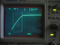
The only remaining question is about the slew rate. You posted a very low (5V/us) value here: http://web.telecom.cz/macura/step_s.gif Is this a scale error, or the VAS current is to small? I hope it's the first...
PMA said:The question still remains. Reduction of distortion after the feedback is applied does not correspond the loop gain.
When VAS is loaded, distortion is decreased. Both in simulation and measurements. We measured several pieces produced, independent people, different measuring gear, same conclusion.
Well, the simulation are predicting a sharp decrease in loop gain when loading the VAS. This is normal. Not increasing the THD can only be because the load has some sort of linearizing effect, reducing the open loop distortions. As I said above, you may want to simulate the open loop distortions with and without the 22k load.
I have to disagree respectfully with everything you wrote about stability.
As I wrote hereabove, I have forgotten to connect the 2.7pF feedback cap into 4 simulated images.
Look what it makes: (and oscillations were above 200MHz, local buffer issue).
Yes THD 1kHz has decreased with VAS loaded.
As I wrote hereabove, I have forgotten to connect the 2.7pF feedback cap into 4 simulated images.
Look what it makes: (and oscillations were above 200MHz, local buffer issue).
Yes THD 1kHz has decreased with VAS loaded.
Attachments

syn08 said:As I said above, you may want to simulate the open loop distortions with and without the 22k load.
As I said above, I had done it. 22k VAS load affects distortion cancellation of NPN and PNP input halves.
PMA said:I have to disagree with everything you wrote about stability.
As I wrote hereabove, I have forgotten to connect the 2.7pF feedback cap into 4 simulated images.
Look what it makes: (and oscillations were above 200MHz, local buffer issue).
Yes THD 1kHz has decreased with VAS loaded.
Well, you posted about the missing 2.7pF before I pressed "Submit reply" in my long message above. Obviously, my whole rationale was based on the results you were posting.
But, bottom line, isn't it that some discipline in methodology and presenting the results is invaluable for providing some common ground for an intelligent technical discussion? These are the first DISPRE results you are posting that really make sense. Please understand that simply claiming something still needs evidence and proof. Except (no pun intended) for marketoids which are usually making a living out of misleading statements, covering the truth, etc...
Re: open loop distortions, was it that loading the VAS linearized the whole open loop amp? It makes some sense, I think I've seen this before, but can you confirm?
What about the slew rate?
I see your point and I agree with most that you have said.
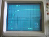
Regarding slew rate, please see measured step response with no RC input filter. This is obtained with 10-100n cap between bases of output transistors. Slew rate cannot be evaluated, as response is still exponential and does not depend on output voltage swing, until clipping.
Regarding slew rate, please see measured step response with no RC input filter. This is obtained with 10-100n cap between bases of output transistors. Slew rate cannot be evaluated, as response is still exponential and does not depend on output voltage swing, until clipping.
Attachments
PMA said:I see your point and I agree with most that you have said.
Regarding slew rate, please see measured step response with no RC input filter. This is obtained with 10-100n cap between bases of output transistors. Slew rate cannot be evaluated, as response is still exponential and does not depend on output voltage swing, until clipping.
Ok, so that's 50V/us. You may want to correct the scale on you website quoted above.
I'll look at the inter-base cap impact, it looks way to high to me, will let you know.
- Home
- Source & Line
- Analog Line Level
- New DISPRE preamp, successor to previous popular version