I've used diamond buffers for high speed line driving a lot. I found long ago that a moderately decent layout and individual 100R base stopper resistors are mandatory for both the drivers and output devices. It's also important to bias the current sources for the drivers with a stiff reference. Either a pair of small signal diodes in series or a voltage divider resistor bypassed with a small capacitor does the job.
Paying attention to that, I've never had an issue with parasitic oscillation.
When PCB real estate is tight (or when fudging a design with no base stopper provision), the base stoppers can be installed above the PCB, in line with the transistor base lead (just cut the base lead off above the PCB and mount the transistor a little higher to make room for the resistor).
Those little 1/8W axial resistors are neat for this aplication.
One (oscillation free) example here (modulator/line driver board):
http://users.picknowl.com.au/~glenk/K160AM.HTM
Cheers,
Glen
EDIT;
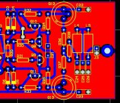
Oh, and local supply rail bypasing at the collector of each output transistor is a good move too. Here is the layout for the modulator board:
Paying attention to that, I've never had an issue with parasitic oscillation.
When PCB real estate is tight (or when fudging a design with no base stopper provision), the base stoppers can be installed above the PCB, in line with the transistor base lead (just cut the base lead off above the PCB and mount the transistor a little higher to make room for the resistor).
Those little 1/8W axial resistors are neat for this aplication.
One (oscillation free) example here (modulator/line driver board):
http://users.picknowl.com.au/~glenk/K160AM.HTM
Cheers,
Glen
EDIT;
Oh, and local supply rail bypasing at the collector of each output transistor is a good move too. Here is the layout for the modulator board:
Attachments
And for your PCB revision, you could add the 68pF caramic (BTW, I though you are in the "ceramic caps bad" team) straight to the ground.
Or even better, try another compensation schema. This one is really suboptimal.
Or even better, try another compensation schema. This one is really suboptimal.
Speak after you have tried and evaluated. Every inductance in series with transistor pins matters. There is nothing like "ground" when we speak HF, inductance of PCB tracks to transistor pins is disallowed. You seem to comment everything, especially the things you have never done.
The oscillations were "local", not a feedback instability. No simulator would show them. They were initiated from OUTPUT of the buffer, usually by impulse when connecting output cable when supply turned on. Please do not recommend higher output series resistor value, it does not help. Only simulation of the buffer itself with parasitic PCB inductances and capacitances included showed the problem.
The oscillations were "local", not a feedback instability. No simulator would show them. They were initiated from OUTPUT of the buffer, usually by impulse when connecting output cable when supply turned on. Please do not recommend higher output series resistor value, it does not help. Only simulation of the buffer itself with parasitic PCB inductances and capacitances included showed the problem.
Syn08,
this is already a low OLG design - the 22k VAS load will not alter the OLG by more than a few % - not worth worrying about I would say.
Pavel, your 68pF cap is connected to the plus rail, which will be decoupled to ground via the power supply. Have you tried connecting the 68pf directly to ground? Might be that with slower loop (100 Ohms and 68pf), the output circuit is not triggered into oscillation by fast rise times. I think Glen has made some useful comments here as well.
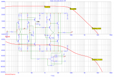
This design may be confusing for those who did not measure the real circuit or do not know the component values. The case is resistor degeneration values of the input stage (very high) and the divider they create with bias resistor. It does not work much like opamp. The CMR is very poor, and only one input can be used. The reason was to prevent input collector current saturation under any conditions of allowed input voltage, even without input RC and ns risetime of input step signal. Openloop gain, after interrupting FB loop, differs from Vout/Vdiff after FB closed significantly, especially without VAS load.
For VAS load 22k, I am attaching openloop curves.
Bonsai, I did try cap against ground directly. It did not stop the oscillations in case they occured. However, I have also changed the PCB groundplane, it has more consistent area near buffer driver transistor now (usually only one channel had oscillated, the one with less ground - higher ground inductance).
Attachments
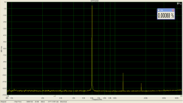
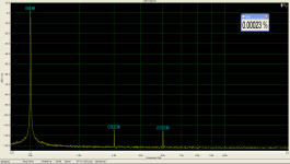
Now, with closed FB, we get this. Distortion is quite low even without FB (my previous post), it is about 0.003%/1Vrms/1kHz. Distortion cancellation.
Because of the flat OLG over the audio band and fast behaviour, not limited by SR, distortion remains same regardless frequency, in audio band.
Because of the flat OLG over the audio band and fast behaviour, not limited by SR, distortion remains same regardless frequency, in audio band.
Attachments
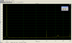
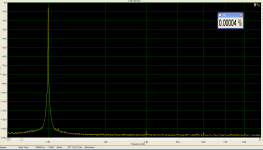
All these measurements are done by a colleague of mine, and my honors goes to him. I am unable to measure such low distortion levels with my equipment. He generates the signal by AP and measures by very good soundcard, both tuned and optimized.
Hereby the measurement limit:
Hereby the measurement limit:
Attachments
To make the confusion a bit higher, I can say that distortion (both measured and simulated) is a bit lower with VAS load 22k, than without load.
He generates the signal by AP and measures by very good soundcard, both tuned and optimized.
I'm confused - why doesn't he use also the AP for measuring? You're not going to tell me his soundcard has more resolution than the AP, are you?
Have fun, Hannes
Nice to see that you have fixed the oscillation! Good work.
Not much to say about the super low distortion measurements...
That sound card is something I would like to have in my setup. I can only measure down to ~0.008% during optimal conditions.
May I ask what soundcard your friend is useing?
Sigurd
Not much to say about the super low distortion measurements...
That sound card is something I would like to have in my setup. I can only measure down to ~0.008% during optimal conditions.
May I ask what soundcard your friend is useing?
Sigurd
PMA said:All these measurements are done by a colleague of mine, and my honors goes to him. I am unable to measure such low distortion levels with my equipment. He generates the signal by AP and measures by very good soundcard, both tuned and optimized.
Hereby the measurement limit:
PMA,
It is of course very difficult to make any kind of evaluation without knowing how your thing is working. For example, using very high degeneration in the input stage is definitely not obvious! Under these circumstances, I wonder though what is your expected feedback when posting these things here? People are trying to help, are making assumptions... You would of course note that I formulated my comments as questions rather than statements...
Here are a few more comments:
- From what you described, it sounds like the amp has issues with capacitive loads. Have you tried to simulate/measure the phase margins in capacitive loads?
- If the cap connected to the ground doesn't help, this may denote a) a suboptimal PCB layout (you already said you are modifying this?) or b) you did not address the core reason for the oscillation problem. Can you post the OLG with and without the cap, in a capacitive load of, say, 100pF? Why don't you think an output resistor (included in the FB loop!), to isolate the capacitive load is not good? I know this is an opamp technique, but it may help here as well...
- I'm stunned by the sound card measurements results. Care to disclose a few details about yours and your friends setups? It's not the resolution (although this is impressive as well) but the lack of noise. In my setup (not sound card based) the noise is the main limitation. Under 10ppm, if somebody farts close to the setup, I may get compromised results. That's why I have to do all sensitive measurements late in the night, when all lights, TVs, etc... are off and from a remote location (upstairs) over the network to avoid any presence, airflows, etc... That's the bast I could do, short of building a Farady cage.
As a side comment, the OLG bandwidth is not that high. If you look at one of my power amps (not a simulation exercise!), it has 8MHz unity gain @200W output and 400V/uS non slewing (your preamp has only 4MHz). Which suggests another approach for your design; rather than trying to insert poles (the new cap, the cap in parallel to the feedback resistor) why don't you try to increase the amp OL bandwidth and then compensate the phase? Of course, I would love to tell exactly how unfortunately, under the circumstances, I can't.
Under these circumstances, I wonder though what is your expected feedback when posting these things here? People are trying to help, are making assumptions... You would of course note that I formulated my comments as questions rather than statements...
I don't see any reason to get personal. I think most of us here have our own preferences for how to design circuits based on trial and errors, using the equipment we can afford or have access to.
Statements is only ones personal belives, not necessary always the truth.......
PMA shares a lot of knowledge and have no shame publishing the problems he encounters with the DisPre II in this thread. Many of us can benefit/learn from this to avoid the same problems.
And could we please get this thread back on track again......
ACD said:And could we please get this thread back on track again......
Was I off topic? I'm sorry, I must be confused about this thread's current topic. Is it about a certain design that currently has reproducibility problems (for which I provided a few suggestions above) or about sales damage control?
jacco vermeulen said:face it, you're on the hit list. (or it's the time of the year)
Nevermind, I'll live anyway
 Not so sure about others if I decide to pull the guns again
 PMA said:
For VAS load 22k, I am attaching openloop curves.
I'm also suggesting you take a second look at the way you are simulating the OL gain. Unless I'm missing something, or there is a discrepancy between the schematics and the curves you are showing in post #385, these results are pretty irrelevant when it comes to stability. It is the loop gain that defines the stability criteria, and simulating the circuit input/output (as apparently you did) simply with the broken loop is not good enough. You may want (if not already) take a look at prof. Middlebrook techique, it's very straightforward for MicroCap users (or ask Edmond, he's the MicroCap guy around).
h_a said:
I'm confused - why doesn't he use also the AP for measuring? You're not going to tell me his soundcard has more resolution than the AP, are you?
It has. Some of the card opamps had to be exchanged for the best ones.
AP - look at Stereophile JA measurements with new AP and compare to these shown here, and tell me where is higher resolution.
ACD said:
PMA shares a lot of knowledge and have no shame publishing the problems he encounters with the DisPre II in this thread.
Thanks, Jan. I have nothing to hide. And I also have no reason to debate with everyone who only irritates (meaning not you, of course).
- Home
- Source & Line
- Analog Line Level
- New DISPRE preamp, successor to previous popular version