Quite large number of units were assembled and produced, and a few of them had strange behaviour. There was a hum and noise in the right channel (designation according to documentation). Also, DC component was unstable when turning the pot.
The reason was oscillation in a diamond buffer, about 200MHz. When measured THD, mains line components and LF noise increased.
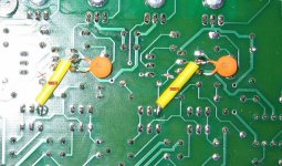
The solution is to add 100R resistor before input of the diamond buffer. And 2 PCB tracks must be cut. Please see the images. I am sorry for the problem.
http://web.telecom.cz/macura/uprava.jpg
http://web.telecom.cz/macura/uprava_zespoda.jpg
http://web.telecom.cz/macura/uprava_100R.jpg
The reason was oscillation in a diamond buffer, about 200MHz. When measured THD, mains line components and LF noise increased.
The solution is to add 100R resistor before input of the diamond buffer. And 2 PCB tracks must be cut. Please see the images. I am sorry for the problem.
http://web.telecom.cz/macura/uprava.jpg
http://web.telecom.cz/macura/uprava_zespoda.jpg
http://web.telecom.cz/macura/uprava_100R.jpg
Also, it is possible, but not necessary, to add R64 and R65 resistors (VAS load). There are free positions on the PCB for them. The value is 22k or 24k.
johnYks said:http://www.lyraconnoisseur.com/Products/Lyra_Connoisseur/files/blocks_image_1_1.png
Inspired by the Lyra Connoisseur?🙂
Yes Sigurd sent me a photo, but I left out the dovetail since it looks like an old drawer, I used tap and groove instead, looks a lot nicer than seeing the joint.
BTW have you completed one, the PCB layout you did was really very good.Sigurd Ruschkow said:That is a heck of a nice box you have for the preamp, Nico! I am glad I sent you the photos of the Lyra Connosieur.
Nico, I think that PMA likes low open loop gain and little feedback but your design is a high open loop design with much FB, IMO.
My version of our line amp has about 30 dB of OL gain and 1 MHz OL freq resp (-3 dB) which I think is more inlie with PMA:s design philosphy.
PMA - correct me if I am wrong here.
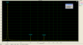
My THD levels are around 0.002% up to about 100 kHz at 1Vrms out and 1k load.
SIgurd
And yes, I remember your preference of low OGL Sigurd. My ultimate goal was zero THD.
Finally, I added only the CCS and optimised the component values of the the original design I did in 1984 for a DC - 15 MHz signal/function generator. Simulators are great design aids.
I have since replaced the transistors with the few original HP branded types I kept.
Even with the common transistors in the prototype, only H2 is bearly visible above the noise floor on the spectrum analyser in 1 Hz BW -140 dB down into 50 ohms. For all practical purposes H3 and higher order products were theoretical.
PMA said:Hi Nico,
we have some new results as well. The feedback is 12dB.
Excellent achievement with so little feedback.
Run it open loop with only a tiny signal before clipping. The THD should only be 12 dB higher, than this then.
Nice work
Yes it is, about 4x higher. It is all about distortion cancellation in input complementary-differential stages, exact BJT PNP-NPN matching and emitter (degeneration) and bias resistor sellection. I cannot get this with JFEts.
PMA said:Yes it is, about 4x higher. It is all about distortion cancellation in input complementary-differential stages, exact BJT PNP-NPN matching and emitter (degeneration) and bias resistor sellection. I cannot get this with JFEts.
See if the design can work safely with 1.5 - 2 x the current rail voltage. THD is indirectly related to supply voltage. This is because distortion is related to second order intercept.
I see an interesting phenomina, I did not look carefully before. You have no even order products and only H3 and H5.
If this is a real signal then look for the problem in the signal generator, it may be generating these harmonics and not the amplifier. Try putting a very high Q passive filter at the output of the signal generator.
Nico
If this is a real signal then look for the problem in the signal generator, it may be generating these harmonics and not the amplifier. Try putting a very high Q passive filter at the output of the signal generator.
Nico
Yes, the design can work with higher supply rails. As is, I would not exceed 2 x 22V.
No, there is only H2 and H3. The base is 2kHz in the last measurement.
No, there is only H2 and H3. The base is 2kHz in the last measurement.
PMA said:Yes, the design can work with higher supply rails. As is, I would not exceed 2 x 22V.
No, there is only H2 and H3. The base is 2kHz in the last measurement.
Sorry as usual I look into my eyelids. Nice work.

I had been fighting against HF oscillations in the output diamond buffer of some of the modules, and found the solution as described in
http://www.diyaudio.com/forums/showthread.php?postid=1690502#post1690502
but a 68pF cap must be added as well. Please see the photo. The modification has been tested since December 22 on several pieces successfully.
I will produce and evaluate version V3 PCB in January, with all the modifications. I will also rewrite my Dispre 2 web page.
Attachments
PMA said:I had been fighting against HF oscillations in the output diamond buffer of some of the modules, and found the solution as described in
http://www.diyaudio.com/forums/showthread.php?postid=1690502#post1690502
but a 68pF cap must be added as well. Please see the photo. The modification has been tested since December 22 on several pieces successfully.
I will produce and evaluate version V3 PCB in January, with all the modifications. I will also rewrite my Dispre 2 web page.
Make sure you also redo the measurements; if the cap is placed where I believe it is, it's going to be some significant impact on OLG, distortions and SR. I'm also curious if this change will affect the sound?
Both simulations and measurements were already done, as well as step response measurements. And listening tests also.
IMHO the circuit is still fast enough for audio use and has flat OLG above audio band.
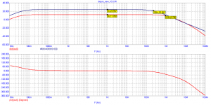
THD spectral analysis shows almost no difference in audio band; step response is longer (rise time 880ns) and preserves same shape for large and small signals.
Simulation shown is without capacitor in input RC filter.
IMHO the circuit is still fast enough for audio use and has flat OLG above audio band.
THD spectral analysis shows almost no difference in audio band; step response is longer (rise time 880ns) and preserves same shape for large and small signals.
Simulation shown is without capacitor in input RC filter.
Attachments
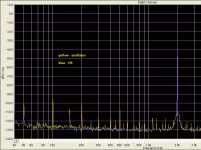
I would like to show the difference between oscillating and non-oscillating status in the same channel. It was pretty tough problem, not seen by scope at the output.
The 68pF cap position may seem strange, but remember they are the PCB parasitic impedances together with fast buffer driver transistors that made oscillation condition to fulfill. It oscillated locally above 200MHz, with almost no change in THD. The cap must be placed directly where it is.
The 68pF cap position may seem strange, but remember they are the PCB parasitic impedances together with fast buffer driver transistors that made oscillation condition to fulfill. It oscillated locally above 200MHz, with almost no change in THD. The cap must be placed directly where it is.
Attachments
PMA said:Both simulations and measurements were already done, as well as step response measurements. And listening tests also.
IMHO the circuit is still fast enough for audio use and has flat OLG above audio band.
THD spectral analysis shows almost no difference in audio band; step response is longer (rise time 880ns) and preserves same shape for large and small signals.
Simulation shown is without capacitor in input RC filter.
I have no doubt that your preamp is still very good. Could you though describe the sound of the modified preamp? The impact of the two caps should be clearly audible.
I guess it has to be a ceramics cap,
but did you try with a polystyrene cap?
For littlest sonical impact.
Sigurd
but did you try with a polystyrene cap?
For littlest sonical impact.
Sigurd
Hello all,
I have tried to describe all the modifications in my web, so please kindly visit
http://web.telecom.cz/macura/dispre2_en.htm
I am recently having problems to reply to e-mails to some of you (johnYks, burbeck, JP ....), my mails are refused by destination servers. I am trying from another address (same server as in the address), but still having problems. Probably too high security setting, sorry to be unable to reply.
Caps 68pF are NPO ceramic.
PMA said:Hello all,
I have tried to describe all the modifications in my web, so please kindly visit
http://web.telecom.cz/macura/dispre2_en.htm
I am recently having problems to reply to e-mails to some of you (johnYks, burbeck, JP ....), my mails are refused by destination servers. I am trying from another address (same server as in the address), but still having problems. Probably too high security setting, sorry to be unable to reply.
Caps 68pF are NPO ceramic.
Something is not right... http://web.telecom.cz/macura/step_s.gif only 5V/uS? It says 0.3V/div and 400nS/div.
The cap is where I was assuming it has to be... But the 22k resistor, if installed, doesn't have a dramatic impact on the OLG (and hence THD)?
- Home
- Source & Line
- Analog Line Level
- New DISPRE preamp, successor to previous popular version