I just installed Guido Tent's Directly Heated Tubes Supplyboards and I am swiped away with the quality and results. Great build, easy to use.
Great depth of sound.
So Guido, kudo's
thanks ! This is why we do it, transparent sound rules !
cheers
thanks ! This is why we do it, transparent sound rules !
cheers
Guido - do you use chokes in the supply to your filaments?
I know Guido and Rod can talk for themselves, but I would say their products are aimed at different users. Guido's VCCS will feed 5VDC to a 300B using a 5VAC transformer, while Rod's regulator, AFAIK, won't do that - therefore Rod's regulator may, maybe, offer even better overall performance.
If one is building from scratch one can account for all the optimalization proposed by Rod, starting with dual chamber PT, choke input supply, etc.
If one has got a working amplifier with hummmm problems, Guido's VCCS will be a fast way to reduce this hummm to very acceptable levels and isolate the PS from Audio by means of the high AC impedance of the CCS.
Hi,
I'd like to ask regarding placement of the Coleman Regulator v7 PCB, the distance between it and the DHT tube. In the assembly manual it says 200 - 250mm (8-10") and I'd like to ask how critical this - and also what the reason for this might be.
Thanks,
LH/S
I'd like to ask regarding placement of the Coleman Regulator v7 PCB, the distance between it and the DHT tube. In the assembly manual it says 200 - 250mm (8-10") and I'd like to ask how critical this - and also what the reason for this might be.
Thanks,
LH/S
Hi - It's a good question. There are two concerns:
I. Longer runs of cable may attract noise from trafos & chokes. If you take care to avoid passing by the B-Field from any Iron, and twist the cables, you can run longer than the recommended length.
II. The new V7 Regulators were design-optimised for even higher dynamic impedance (as the filament sees it). Long runs of thick cable can begin to add leakage capacitance, and if this is not controlled, could affect the measurements at high frequency. The improved sound of the V7 is probably due to the higher impedance, and the improved supply isolation, and since most constructors use them with a view to sound quality, it may be worth taking extra care.
So the answer is that if you are confident about noise-sources, and measuring cable capacitance (and even cheap DMMs measure capacitance quite accurately, today), then you can go ahead and extend the cable. But with preamps, and as a general rule, it is best to stick to the recommendation.
One effect is of no concern: stability. The design was characterised during development to include stability with a 3 metre cable - with no static or transient effects found - tested with 50mA, 1A/2A and 5A filaments.
Thanks Rod,
My misinterpretation - I was thinking it suggested a minimum distance to the socket ie. no closer than 8-10" and scratching my head.
Definitely will follow the recommendations and on that would like to ask regarding R3, C3 and C6 as per the manual and how it might relate to the following application (not drawn in for sake of simplicity).
Particularly with C6 - with all these transformer primaries in parallel as seen reflected back across the isolation transformer. Seems R3, C3 perhaps not as critical but any insight is greatly appreciated.
Thank you.
LH/S
Attachments
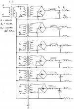
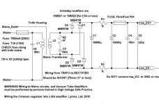
Hi - Yes, The snubber network R3-C3 can be applied to all of the secondary windings in your (multiple trafo) application. Apply separate R3-C3 to each one.
C6 is a mains suppression capacitor. the 0.1µF value will work well enough here, if you are already adding an isolation transformer. The incoming mains noise will be reduced to very low levels already.
Without an isolating trafo, the noise suppression improves with larger values of capacitor, but this is regarded as hazardous, since pulling out the mains-supply plug may leave the cap charged (to as much as 350V dc or even higher), and present a risk to someone touching the pins of the mains plug.
Adding a suitably voltage- and power-rated Flameproof resistor (e.g. 1M ohm) across the cap will reduce risks, by discharging it reasonably quickly.
Attachments
Thanks Rod - with C6 would you add one to the isolation transformer primary as well??
LH/S
LH/S
Last edited:
Yes, if you use an extra isolating trafo (double-layered isolating) you can increase the size of the « isolated » C6, because that capacitor cannot present a hazard to a person touching the disconnected mains plug. So 1µF or even more is usable here.
The C6 connected directly to the mains supply should be 0.1µF and be a safety rated X2 type.
The C6 connected directly to the mains supply should be 0.1µF and be a safety rated X2 type.
Yes, if you use an extra isolating trafo (double-layered isolating) you can increase the size of the « isolated » C6, because that capacitor cannot present a hazard to a person touching the disconnected mains plug. So 1µF or even more is usable here.
The C6 connected directly to the mains supply should be 0.1µF and be a safety rated X2 type.
Thanks again Rod,
Any benefit from moving from 0.1uF to 1uF X2 rated caps for the isolated primary windings (plural) as per schema?
LH/S
Last edited:
Xc=1/2*pi*f*C
1uF at 50Hz about 3.18k.
230V/3.18k= 72mA
Dissipation of 1uF is 16.6W.
I understand the math, but I dont understand the question in 'what frequencies we are trying to filter'.. and so I just shoot straight for the simple question - what value of capacitance 🙂 and leave the answer to those who know more about this stuff than me..
0.22uF and call it a day?
LH/S
It's OK. 1µF will draw current, but this is a reactive load - the power-factor is near to zero, so no power is dissipated, except in the minor series-resistance.
Read up on reactive power here:
True, Reactive, and Apparent Power : Power Factor - Electronics Textbook
I recommend a fairly high value of capacitor, rated for safety X2 class, and 275V ac is a usual voltage rating. 0.47-1.0µF will be fine. The higher value for 120V intermediate voltage, lower will suffice if you have 230V.
I just installed Guido Tent's Directly Heated Tubes Supplyboards and I am swiped away with the quality and results. Great build, easy to use.
I use it SE. I have the plus on pin 1 of my 300BC (carbon plate, like a 211) and also I have the cathode resistor there.
My Chinese 300BC have a slight imbalace in the winding; in pushpull and AC it can be balanced quite well, but not on a SE application. And then: even a normal DC feed, CCS, shunt still gave some mains lines disturbances.Great depth of sound.
Now it is quiet as night.
So Guido, kudo's
Apart from sounding clean, it measures alike very clean.
I just like to add that with Guido's circuit the 300B anode (disconnected grid from driver) has less than 0,2 mV of 'noise', that is, the scope line is a bit thick, no 50 or 100 Hz residues at all, no mains flicker.
I can push the driver to 200 Vpp, this can be seen in the decoupled situation because of a minimal earth coupling (I have a bus). This shows as a small residue on the 300B anode, about -100 dB, very clean.
The driver still has its AC heater noise bursting through, and amplified at the 300B anode this is about 2-4 mV, the usual nervous and jagged 50 Hz mains structure, so I should go to DC heating of the driver to get it all clean. Next project.
It's OK. 1µF will draw current, but this is a reactive load - the power-factor is near to zero, so no power is dissipated, except in the minor series-resistance.
Read up on reactive power here:
True, Reactive, and Apparent Power : Power Factor - Electronics Textbook
I recommend a fairly high value of capacitor, rated for safety X2 class, and 275V ac is a usual voltage rating. 0.47-1.0µF will be fine. The higher value for 120V intermediate voltage, lower will suffice if you have 230V.
Thanks Rod,
I'll split the difference between 0.47 and 1uF and lock in 0.68uF.
Cheers,
LH/S
I'm not sure if this is appropriate to ask but does anyone have a schematic or know the general design concept of the tentlabs filament supply? I want to DIY my own.
The best I gather is that it's a differential amplifier feeding a V-reffed integrator into a VCCS.
Does this sound correct?
The best I gather is that it's a differential amplifier feeding a V-reffed integrator into a VCCS.
Does this sound correct?
I'm not sure if this is appropriate to ask but does anyone have a schematic or know the general design concept of the tentlabs filament supply? I want to DIY my own.
The best I gather is that it's a differential amplifier feeding a V-reffed integrator into a VCCS.
Does this sound correct?
The tentlabs filament supply is my design and copyrighted. I have put a lot of effort in it to design, manufacture and support the product as it is. I make a living of designing, manufacturing and selling modules. I also employ people who contribute, who I pay. They can buy houses, have a living. This is an economy that supports all of us, including yourself. Copying the design let alone publish it potentially threatens such economy. It is up to you to decide if it is appropriate to ask for schematics.
The concept is explained at my website.
best,
Hi Adrien,
Yes, Connect the positive side of the filament to system ground, for best results. The regulator version makes no difference to this. You can try it with negative to ground, if you like, since the sound quality is the chief concern. BUT, the bias (anode current) is affected by the choice of +/- to ground, so please make adjustment of bias voltage, to compensate for this effect, before listening, and comparing.
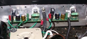
I'd like to report that my upgrade from v4 to v7 went well. The change to one mount point in the middle wasn't a big deal to rework. The transistor separation changed but I just leaned them inward and used the same heatsink holes. There is a noticeable improvement with the sound as others have reported. My amp is all DHT and I upgraded all 4 regulators. Thanks very much for the v7 Rod. Well done!
Attachments
I just ordered 6 regulators. Planning a Bartola 01a line stage for one pair and a PP differential driver stage for the other 4. If anyone has any experience along the PP line I would very much like to know how it worked out. I'm probably several months away from having it ready to try. I think I will work the line stage first.
Thanks,
John
Thanks,
John
PP differential driver stage for the other 4.
PP differential driver with direct heated tubes? 10Y with transformers?
IMHO using R.C. regulators for indirect heated tubes is wasting of money.
- Home
- Amplifiers
- Tubes / Valves
- New DHT heater