Hi James,
The new V7 incorporates all the refinements I could come up with over the 3 years the V4 was in service. The best updates: the V7's dynamic impedance looking out of the filament is now higher and flatter (vs freq.) - and is the reason for the reports here of improved sound. The V7 also works with a lower headroom of supply voltage - about 1V lower - so they can run cooler.
But the V4 will still give excellent performance - enjoy those DHT amps!
Hi Rod,
Thanks for the info! I am curious if one uses Battery Power supply for the regulator / gyrators, would it sounds better than commonly used LCR type DC supply to the gyrators?
I will be rocking with the V4 boards for now. I will contact you when I am ready to move to V7 boards.
Last edited:
Hi Rod,
I have the V-4 version regulators for my 4p1l preamp, now i want to change the operation point to 30ma with a filament bias resistor of 15 ohm
Do i need to change r8 which is now 1k ?, C1 is 100uf /16v
Raw power supply would be 16,5vdc
Thanks...
I have the V-4 version regulators for my 4p1l preamp, now i want to change the operation point to 30ma with a filament bias resistor of 15 ohm
Do i need to change r8 which is now 1k ?, C1 is 100uf /16v
Raw power supply would be 16,5vdc
Thanks...
Raw power supply would be 16,5vdc
If you don't use starving (filament current is 650mA), the 16.5V raw DC is on the border.
The 4P1L (hot) filament resistance is 3.23R. With 15R bias resistor the sum is 18.23R.
18.23R*0.65A = 11.85V
The V4 regulator needs at least 5V, thus raw DC would be at least 16.85V.
I use 15VAC (60VA) transformer, good schottky graezt (MBR1645: 0.63V forward voltage), 4700uF, 1R (in both line), 10000uF, so output raw DC is 18.5V.
Hi Rod,
Thanks for the info! I am curious if one uses Battery Power supply for the regulator / gyrators, would it sounds better than commonly used LCR type DC supply to the gyrators?
I will be rocking with the V4 boards for now. I will contact you when I am ready to move to V7 boards.
Sorry to miss seeing your post earlier.
Battery power makes little difference to the Filament Regulators, as they can reject ripple so strongly, and leave only microampère level noise & ripple.
But in some amplifier layouts or where the raw dc rectifiers are a little too close to sensitive wiring, or preamps, or DACs, it's possible that moving to battery power may eliminate this kind of noise coupling. OTOH, if the trafos are a safe distance from everything, this will make little difference, too.
Enjoy the DHT sound!
Hi Rod,
I have the V-4 version regulators for my 4p1l preamp, now i want to change the operation point to 30ma with a filament bias resistor of 15 ohm
Do i need to change r8 which is now 1k ?, C1 is 100uf /16v
Raw power supply would be 16,5vdc
Thanks...
Hello Martin,
Please use R8 = 3.3KΩ for 16-21V supply range.
I'm having troubles with my filament bias...or so it seems.
Setup:
4p1l as driver tube. Transformer coupled to a 300b.
16 ohm bias resistor. Rod's boards. 245V on the b+ of the interstage transformer for the 4p1l.
What I've done:
Without b+ set the voltage across the filament resistor to 10v so more or less 625mA on the filament.
When I turn on the amp though. I measure the voltage drop across my interstage. Resistance is 327. The drop is 27v. Which means the 4p1l is drawing 82mA
What am I doing wrong?
Last edited:
I'm having troubles with my filament bias.
Anode voltage?
Filament bias voltage (10V+Ia*16)?
Grid voltage? Grid leak resistor -measured- value?
218 or 245 can't remember for sure. Just remember for sure the voltage drop across interstage is 27v.Anode voltage?
Don't know the grid voltage. Grid leak resistor 47k I think.Grid voltage? Grid leak resistor -measured- value?
't was late last night.
The Grid leak check is a good tip - old 4P1Ls may be gassy, and the data-sheet value of 500KΩ may be too high.
Or you could short the grid to 0V(B) - Ground.
Also - please check the raw dc is not grounded anywhere, or connected to chassis - this could upset the biasing badly! Please disconnect and measure - both sides of the raw dc must measure no leakage to chassis/ground.
Enjoy those 4P1Ls!
Or you could short the grid to 0V(B) - Ground.
Also - please check the raw dc is not grounded anywhere, or connected to chassis - this could upset the biasing badly! Please disconnect and measure - both sides of the raw dc must measure no leakage to chassis/ground.
Enjoy those 4P1Ls!
Looks like I got some lemon 4p1l 🙂 🙁. The first one..basically just shorted after 10 seconds...drawing a massive amount of current b+ went down to 127v. The second one draws 82mA. (Batch from 1969)Enjoy those 4P1Ls!
Last edited:
Surprise to see two bad ones in a row, unless the vendor is deliberately sending out rejects.. Probably worth checking the raw dc-ground leakage, as this could bias them wrongly.
218 or 245 can't remember for sure.
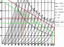
Correct..... for -10V grid voltage and above 80mA anode current.....if you have a plan to melt 4P1L. 🙂
Between 220 and 240V and 20-30mA (-18V grid voltage on 28R bias resistor) are the safer operating points. 😛
I prefer lower anode voltage (for example 160V) and 30-40mA anode current (-10V grid).
Attachments
I'll lower the b+. 🙂 Thanks.I prefer lower anode voltage (for example 160V) and 30-40mA anode current (-10V grid).
160 on the plate. Current is around 34mA. Thanks Euro21. [emoji2]
Sent from my Nexus 6P using Tapatalk
Sent from my Nexus 6P using Tapatalk
Hi Rod
I am planning to use your filament supply boards on a pair of Manley 300B.
Can I use the inboard trafos to power the regs ? Maybe I need a voltage doubler...
I am not sure about how to connect the cathode resistors... would you care to explain based on the schematic in attach ?
Best
Ricardo
I am planning to use your filament supply boards on a pair of Manley 300B.
Can I use the inboard trafos to power the regs ? Maybe I need a voltage doubler...
I am not sure about how to connect the cathode resistors... would you care to explain based on the schematic in attach ?
Best
Ricardo
Attachments
Hi Ricardo,
The Manley uses a standard-recovery bridge-rectifier, and connects its dc output directly to the filaments. This means that the music signal-current in the filament will be mixed directly with the capacitor re-changing pulses, and the rectifier-recovery pulses (which are big, with standard-recovery bridges).
The sound will be improved very much, with properly implemented current-driven heating.
A doubler would probably give about the right voltage, but draws about 4,2A rms from the secondary winding - compared to about 2,2A rms from the bridge.
So the trafo would need to supply an extra 20VA for a pair of 300B filaments. This is probably OK for a large (250-300VA) trafo - but may be hard if the trafo is small, or if it gets hot already.
The cathode resistors must be connected exactly as in the manuals for the regulators -
I'll send some info.
- Home
- Amplifiers
- Tubes / Valves
- New DHT heater