Gyrator circuits are very sensitive (Reducing Power Supply Ripple and Noise and the thread from Keantoken, CFP cap multiplier) therefore not really adapted for DIYer.
Why not only a battery (f+) and a current sink(f-)?
Why not only a battery (f+) and a current sink(f-)?
Question for Rod Coleman about the DHT fillament supply: from your comments earlier I'm led to understand that the impedance the filament looks into on both sides of should be high. However, your circuit has quite a low impedance both when looking from the filament into the gyrator, and looking from the filament into the CCS. What I'm saying, is that it appears to me that neither the output impedance of the gyrator nor the input impedance of the CCS is high. I'm a bit confused by this and the earlier comments on impedance that can be found in this thread.
Hi Iko.
high impedance is required at several nodes, but not in all directions. The performance points that are important are:
- Signal impedance from end-to-end of the filament should be high, so that the regulator does not divert cathode (music signal) current from flowing around the filament, as if the regulator were not there.
It does not have to reach megohms for this to be effective - just big compared to the 1 to 10 ohms of a filament. The small signal impedance looking from the filament into the CCS is several K ohms under the worst case conditions, so I think it qualifies. As such, the impedance looking from the filament through the gyrator is not really important.
The impedance looking into the gyrator from the filament is not high impedance, but this side is usually grounded in the application, and this is not of any consequence.
- In the second case, the insertion impedance (the small signal broadband series impedance) looking from the power supply raw dc to the filament should be as high as possible. This is to isolate the filament from rectifier artefacts and mains borne noise. In the case of my regulator this impedance is effectively determined by the output capacitance of the pass transistors: 30 to 250pF, depending on the model, and standoff voltage. This provides high insertion loss up to pretty high frequencies, and works notably better than 3-terminal regulators in this regard - one reason why it sounds so much better!
It does not provide high impedance in every direction, but provides high impedance across the boundaries that are important in the application.
Both these major considerations are aimed at allowing the signal current to pass unmolested (by noise or by low impedance, due to feedback).
I'm just trying to wrap my mind around the whole discussion that the filament should see high impedance on one side, so that the signal currents go the other side. I understand that the gyrator is more a power supply filter, so it should have a high input impedance. In face it has quite a low output impedance. Let's put this issue aside for not. From what I understand, the circuit should be used such:
+vcc->gyrator->filament->cathode resistor->ccs->ground
Now let's look at the CCS. It should or it should not have a high input impedance?
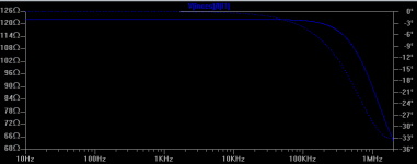
This is what it simulates like, using ZTX894, MJE15032, and a current of about 1.28A through the filament.
+vcc->gyrator->filament->cathode resistor->ccs->ground
Now let's look at the CCS. It should or it should not have a high input impedance?
This is what it simulates like, using ZTX894, MJE15032, and a current of about 1.28A through the filament.
Attachments
I'm just trying to wrap my mind around the whole discussion that the filament should see high impedance on one side, so that the signal currents go the other side.
see my presentation from 2003 here
http://tentlabs.com/Components/Tubeamp/Tubefilament/assets/Heatingmethods.pdf
best
Thanks Guido, I read it. It did not answer my question. From what I understand your circuit has one side of the filament "closer" to ground, while the other one presents a high impedance to the filament, right?
The gyrator does not need a high input impedance. Instead it needs a high impedance across to the filament; the fact that it has a low impedance to the raw dc negative is not of great consequence, but in fact it dissipates noise. Both these properties are material aid to keeping the mains and rectifier disturbances from reaching the filament.I'm just trying to wrap my mind around the whole discussion that the filament should see high impedance on one side, so that the signal currents go the other side. I understand that the gyrator is more a power supply filter, so it should have a high input impedance. In face it has quite a low output impedance.
From what I understand, the circuit should be used such:
+vcc->gyrator->filament->cathode resistor->ccs->ground
This assignment will cause confusion. Please think of:
raw dc +ve > Gyrator > (HT ground) > filament > CCS > Raw dc Neg.
Now let's look at the CCS. It should or it should not have a high input impedance?
This is what it simulates like, using ZTX894, MJE15032, and a current of about 1.28A through the filament.
It should, and in fact does have, high impedance looking into the collector side of the CCS.
The simulation results should be better than that, but only if the models are trustworthy - and the right ones are used! And, the circuit and circuit operating conditions must be accurate.
That is chiefly down to the use of the transistor in the version of 7 years ago. although it works and sounds OK, the MJE15032 is now neither used nor recommended. The saturation region of this part is not very flat. Today, 2SC3852 and a number of other (all Japanese) equivalents are used, and give hugely better performance, especially at low Vce found in this application. The dynamic impedance of the completed circuit measures in the Kohm region.
You don't need to take the trouble of simulating to find this out for yourself: just look at the saturation region curves of a good transistor. All the models of regulator I supply operate with the Vce-Ic characteristic in the horizontal region, ie high impedance. And, since there is no feedback, or any other circuit element connecting to the filament, or collector, this performance is upheld in the actual regulator.
This assignment will cause confusion. Please think of:
raw dc +ve > Gyrator > (HT ground) > filament > CCS > Raw dc Neg.
Thanks Rod. I don't see the cathode resistor connected to the filament.
I'll think about your other comments a bit more.
Thanks Guido, I read it. It did not answer my question. From what I understand your circuit has one side of the filament "closer" to ground, while the other one presents a high impedance to the filament, right?
My suggestion indeed is to connect one end to ground, the other end sees a high impedance, hence the differential cathode impedance is high, which is what counts.
best
Thanks Rod. I don't see the cathode resistor connected to the filament.
I'll think about your other comments a bit more.
Does this old drawing help, regarding the connexions?
The CCS to filament interface is a collector of an NPN, which should always be high impedance, if the operating voltage/current is appropriately chosen.
Think of the Gyrator as a noise buffer, more than any other purpose.
Attachments
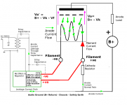
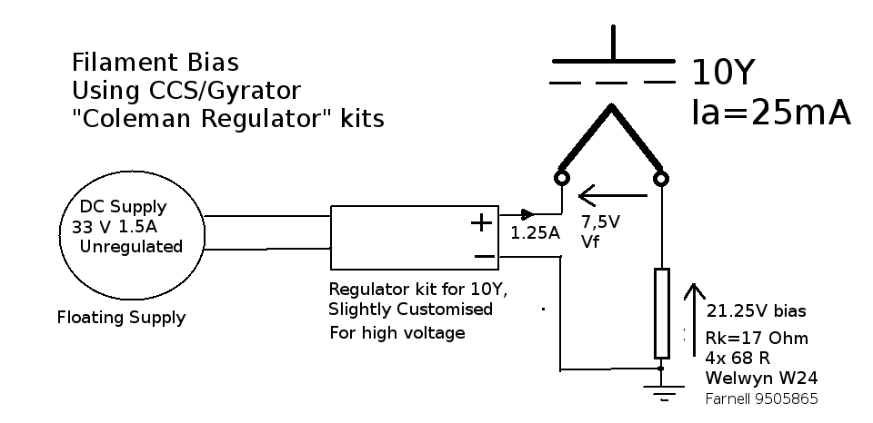
It's a bit different from this one:
I should say, I'm really not trying to give you a hard time. People like the effect on sound when using your circuit, which I'm not disputing. Just want to understand better why it works.
I should say, I'm really not trying to give you a hard time. People like the effect on sound when using your circuit, which I'm not disputing. Just want to understand better why it works.
It's different only in the polarity of the filament.
Originally, I believed that returning the anode through the negative should be best, and I think that Western Electric even counselled that orientation. But, including contributors on this thread, it quickly transpired that the positive return sounds best. I cannot give and solid explanation for why it should be, but it appears so.
There are many reasons why my regulators are preferred by nearly everyone who's done any kind of comparison (see the comments in this thread, and other boards). Chiefly, there's no noise-generating reference of any kind in the circuit, since only a Vbe is used for current control (a few n/(Hz^0.5) if done right). It also blocks noise from the mains and rectifiers better than most other solutions, and hugely better than 3-terminal regs. Also, you'll find that filament regulators must avoid sensing the cathode signal, as completely as possible, for success. This is one of the reasons that voltage-controlled regulators perform badly. Think about a transient error of say, 0.2% in a filament current of 1.25A, and compare it with the value of the cathode current, to grasp why that is important. Remember that the cathode current and the filament current flow in the same conductor, and noise & transient errors are 100% conveyed from the brutal filament supply, to the delicate cathode signal!
Possibly. But knowing Andy, he will have tried both ways, and chosen the best sounding.
As I say, I don't have any analysis to address the polarity question. At worst, it affects the way the cathode current is contained locally, as opposed to getting out toward the supply transformer. It does not affect the architecture or operation of the filament current regulation.
Buyers of the kits receive detailed instructions on how to get the best out of their DHT, by optimising the heating supply. Among the suggestions is to try the cathode return both ways - starting with positive, since this seems the orientation most often preferred.
http://www.diyaudio.com/forums/tubes-valves/38248-new-dht-heater-4.html
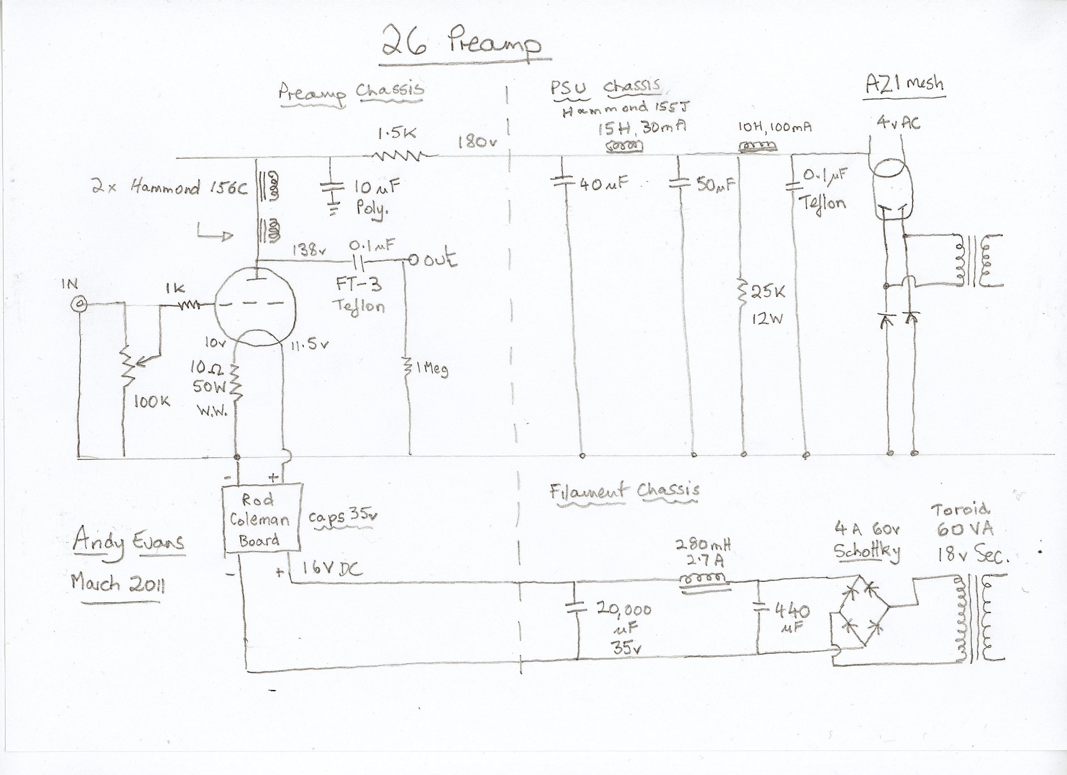
The above is what I've been using until recently - Rod's original design in post 35 of this thread. The gyrator goes to the plus and the current source to the negative, i.e. ground in filament bias.
I wasn't aware I could connect it the other way around - is this true?
andy
The above is what I've been using until recently - Rod's original design in post 35 of this thread. The gyrator goes to the plus and the current source to the negative, i.e. ground in filament bias.
I wasn't aware I could connect it the other way around - is this true?
andy
On a side note I think it is confusing to think of this as gyrator-filament-CSS (or the other way around.) Especially when you are directly connecting one end of the filament to ground!
I see it as Gyrator feeding CCS||cathode.
I see it as Gyrator feeding CCS||cathode.
http://www.diyaudio.com/forums/tubes-valves/38248-new-dht-heater-4.html
The above is what I've been using until recently - Rod's original design in post 35 of this thread. The gyrator goes to the plus and the current source to the negative, i.e. ground in filament bias.
I wasn't aware I could connect it the other way around - is this true?
andy
Andy, Iko & I were talking about the question of whether B+ Return (i.e. Chassis, or real Ground - or the cathode resistor, or LED) should be connected to the filament's positive or negative.
It does make a big difference. you have to use a different value cathode resistor, if you use cathode bias, or adjust bias voltage if you use fixed bias - because the bias is shifted by an amount equal to the filament voltage, when you switch polarity like this.
It is well worth trying, to see which way round you like it best.
However, in your drawing filament bias is used! In this arrangement, there is no choice in the polarity - the negative must connect to the cathode bias resistor, or else the bias will be reversed.
But in all other applications, trying positive-return is recommended..
On a side note I think it is confusing to think of this as gyrator-filament-CSS (or the other way around.) Especially when you are directly connecting one end of the filament to ground!
I see it as Gyrator feeding CCS||cathode.
It's worth remembering that the whole filament supply - especially the AC transformer secondary, and rectifier/caps floats.
It's only ever connected to ground at one point (Fil + or Fil -) - this is for the cathode current only. The filament current does not need to even know that Ground exists - (ie B+ Return, or B-, or 0V (HT)).
One of the regulator's functions is to isolate GND from the filament supply.
I guess thats where we get confused. I wouldn't say it is possible to have a floating heater supply on a DHT (even AC.) I would say the CCS allows it to "approach" floating. Even though the filament current doesn't need the ground it is still connected and this can't be dismissed? Possibly for all practical use it is insignificant, like say even 100db lmW sensitive headphones?
- Home
- Amplifiers
- Tubes / Valves
- New DHT heater