I've pretty much decided on the electric part. But I'm still thinking how I'm going to do physical side of things.Mine is finally getting built but it has taken a long time..
I have for the gm70. A plate choke, output transformer, separate filament transformer, power transformer, interstage, a psu choke and a massive capacitor 45uF/5000V. Then Rod's filament board, with its psu. Then I'm planning a separate power transformer for each of the two preceding stages. It'll probably be some kind of tower.
Good luck with yours and be careful.
hello Rod,
Thanks for your comments. I am following your work here once and a while, and would like to ask you why you create high impedances at both sides of the filament ? Oe of the ends should be connected to ground (or cathode resistor) anyhow, hence sees a low impedance to ground.
The downside of 2 active devices at each side is heat dissipation, you'll probably be aware of that 🙂
Since I deliver to a variety of customers, I decided to optimize for low dissipation as well, hence the single FET.
keep up the good work
best
Guido
Thanks Guido,
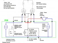
There's two main reasons for regulation on both sides of the filament - an open-loop voltage regulator (Gyrator) on one side, and current regulation on the other.
1. The filament transformer secondary must be floating. This means that any noise coming from the mains, or the rectifiers is common-mode (referring to system Ground). To keep the noise out of the cathode circuit, both sides of the filament are buffered with transistors.
2. I found that many regulation circuits with high gain have a negative influence on the sound. I suspect that this is because the amount of *anode* current running in the filament (maybe 50mA) is badly affected by the transient behaviour of a high-gain regulator loop trying to control 1.3A (say, in a 300B).
For instance, a 0,4% regulation overshoot is 10% overshoot in anode current!
So, I made the control loop low gain, and having regulation on both sides of the filament helps to reduce the ripple current in the filament to minute levels, without much gain. It also means that no reference voltage is needed, and together with a 1-transistor control loop, the noise added by the regulator is the lowest possible - only a few nV/rt Hz from the transistor.
The circuit used for the kits is very like the one I posted all those years ago, with some refinements to reduce the noise even lower. I tried all kinds of other architectures, but only found ways of degrading the sound, compared to the original!
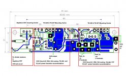
Gianluca, The PP circuit is designed, PCB finished.... but I did not fabricate any yet - the demand was not high enough, so far as I can tell.
Perhaps when the SE PCBs are all sold, I can buy some more - with the PP circuit in a panel.
The PP circuit includes positions for IXYS or DN2540 depletion FET - to use as a cathode-circuit CCS.
The layout is designed for up to 10A filaments!
Perhaps when the SE PCBs are all sold, I can buy some more - with the PP circuit in a panel.
The PP circuit includes positions for IXYS or DN2540 depletion FET - to use as a cathode-circuit CCS.
The layout is designed for up to 10A filaments!
Attachments

Rod
that looks nice. I am wondering what would be the advantage in using DC heating for push pull amps where the hum will be cancelled by the (anti)symmetry of the amp. I have a limited experience with PP amps hence the question.
In the 801A (single ended) amp I am currently building I am indeed using the second pair of regulators you sent me and a choke input raw DC supply to avoid all the high freqs noise a conventional/more practical C input supply would generate, this should make things easier for the regulator but maybe mine is just an overkill. Do you have a guess/measurement of the noise rejection ration of the regulators?
Gianluca
intersting Gianluca ,need row psu too for 801 ,I'm thinking choke input with hammond 159zc ....
Gianluca, keep in mind that the DHT filament is the cathode - and if you wire the cathode to a heating trasformer, there will be capacitive leakage from your cathode circuit to the safety ground of the transformer core. Via nasty dielectrics!
The regulator buffers the filament from this leakage path, and in the opposite drection, gives isolation from rectifier pulses. These may have broadband spectrum, and not be rejected by the PP action..
Thirdly, the difference in voltage across the filament (instantaneous in ac, constant in dc) means that some anode current flows through the filament. Connecting a transformer secondary across the filament causes some of this current to run right around the transformer secondary (it is much lower resistance than the filament, but with some inductance and leakage capacitance). Now you have a leakage path with frequency dependent characteristics - nasty!
It's even worse with dc supplies ending with an electrolytic capacitor - now your parasitic path for the stray anode current is a bad dielectric, again with frequency nonuniformity. And if the cap value is below about 47000uF, there is LF rollof as well as HF.
The ripple rejection of the regulators:
For optimum supply voltage (about 5V above filament voltage), the Gyrator section will reject 150mV of incoming ripple (typical value if you build the raw supplies according to the manual) down to about 4mV.
The CCS section then reduces the ripple *current* to well below 1mA - I'll have to build a scope preamp to see how far below.
The advantage of the choke input remains though - that you can avoid the big capacitor charging pulses in the raw dc. supply. These pulses [maybe 5A in a 1A supply] can work their way back up the mains supply and trouble your preamp, unless precautions are taken.
Also, the danger of EM coupling from the pulses, into other circuits, is reduced.
Hi Rod,
If you have the PP board produced, I'd still like to buy some. I've recently breadboarded a PP 6B4G amp which sounds pretty good so far, but it could really use your boards for hum reduction.
Thanks,
John
If you have the PP board produced, I'd still like to buy some. I've recently breadboarded a PP 6B4G amp which sounds pretty good so far, but it could really use your boards for hum reduction.
Thanks,
John
Thanks Guido,
1. The filament transformer secondary must be floating. This means that any noise coming from the mains, or the rectifiers is common-mode (referring to system Ground). To keep the noise out of the cathode circuit, both sides of the filament are buffered with transistors.
2. I found that many regulation circuits with high gain have a negative influence on the sound. I suspect that this is because the amount of *anode* current running in the filament (maybe 50mA) is badly affected by the transient behaviour of a high-gain regulator loop trying to control 1.3A (say, in a 300B).
For instance, a 0,4% regulation overshoot is 10% overshoot in anode current!
So, I made the control loop low gain, and having regulation on both sides of the filament helps to reduce the ripple current in the filament to minute levels, without much gain. It also means that no reference voltage is needed, and together with a 1-transistor control loop, the noise added by the regulator is the lowest possible - only a few nV/rt Hz from the transistor.
The circuit used for the kits is very like the one I posted all those years ago, with some refinements to reduce the noise even lower. I tried all kinds of other architectures, but only found ways of degrading the sound, compared to the original!
hello Rod,
1) I don't see the problem. If one side of the filament is grounded, noise cannot enter the cathode circuit. The other side is a high impedance but not grounded; same applies.
2) My circuit does not have any overall feedback in the audio band
The output ripple voltage (100Hz) from my regs is about 200uV (typically, when using 300b), the noise level is about 1uA/SqrrtHz.
best,
Guido
Last edited:
Hello Guido,hello Rod,
1) I don't see the problem. If one side of the filament is grounded, noise cannot enter the cathode circuit. The other side is a high impedance but not grounded; same applies.
2) My circuit does not have any overall feedback in the audio band
The output ripple voltage (100Hz) from my regs is about 200uV (typically, when using 300b), the noise level is about 1uA/SqrrtHz.
best,
Guido
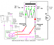
the filament transformer secondary & rectifier are floating, and so noise conducted through them (eg from mains supply), or generated there, is common-mode noise. The rectifier recovery pulses can generate common mode noise *currents*. Without a barrier against noise, circulating currents are possible, as shown in the drawing.
With a cathode resistor, the potential for problems is clear, but even with Rk=0 (fixed bias), you have noise currents circulating in the ground wiring, which risks degrading the sound.
My remarks about loop gain have to do with the *current-control* loop - and the transient behaviour of a 1.3A loop, with its potential impact on the 50mA anode current running through the same conductor.
Attachments
Hi Rod,
I'm testing the pcb's now with the GM70.
Raw DC voltage is around 25V.
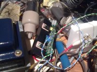
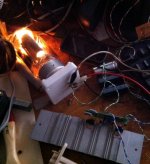
I can dial in the voltage on the filament of the GM70 perfectly to 20VDC. However as the parts become hotter and hotter. The voltage slowly goes down. When it hits around 17v I chicken out and aim a cooler fan onto the circuit and then the voltage ramps up slowly again to 20v. Take it away and it slowly goes down in voltage.
q3 goes over 70 degrees celcius. And q4 and q5 go over 50 degrees.
Is this simply a case where the heatsink is not sufficient? Or maybe these pink pads used as heat conductor just don't work good enough compared to the white paste?
I've included a picture taken with the crappy camera of my phone. But it gives you an idea of the size of the heat sink at least.
Thanks in advance.
I'm testing the pcb's now with the GM70.
Raw DC voltage is around 25V.
I can dial in the voltage on the filament of the GM70 perfectly to 20VDC. However as the parts become hotter and hotter. The voltage slowly goes down. When it hits around 17v I chicken out and aim a cooler fan onto the circuit and then the voltage ramps up slowly again to 20v. Take it away and it slowly goes down in voltage.
q3 goes over 70 degrees celcius. And q4 and q5 go over 50 degrees.
Is this simply a case where the heatsink is not sufficient? Or maybe these pink pads used as heat conductor just don't work good enough compared to the white paste?
I've included a picture taken with the crappy camera of my phone. But it gives you an idea of the size of the heat sink at least.
Thanks in advance.
Attachments
Last edited:
Rod
last comments of yours made a lot of sense to me. I'd be in for a pair of PP boards if you can run a batch. If I may suggest, I'd prefer to have a cascoded 2540 in the cathodes or maybe something beefier as a couple of 300Bs will exceed the 100mA datasheet limit of the 2540.
Gianluca
last comments of yours made a lot of sense to me. I'd be in for a pair of PP boards if you can run a batch. If I may suggest, I'd prefer to have a cascoded 2540 in the cathodes or maybe something beefier as a couple of 300Bs will exceed the 100mA datasheet limit of the 2540.
Gianluca
Bas, 25V supply is perfect for GM70.
With typical filement current of 3,0A [spec is 2,7 .. 3,3A] you'll be burning about 7W in Q4 and similar in Q5. The heatsink you have there looks like an Aavid KM75 - which gives around 5K/W if air circulation is free. With 14W of heat, the parts are in danger of exceeding 100 deg C if the air is not free to move around the fins.
With big transmitter DHTs, best heatsinking is something like a piece of the chassis rear panel. I tested the GM70 regulators on some 3mm thick Alu chassis, 275mm x 100mm, and with 26V in, and 3,3A - the heatsink reached 45 deg C after a couple of hours. Or use a catalogue heatsink with a rating of 1,5 .. 2K/W or better.
There is something wrong if Q3 is hot. This does not burn any serious power. please check the value of R8 is correct. Measure voltages at R8: top should be about 23,5V, bottom about 3,6V for GM70 with 25V input.
Bas, the GM70 voltage will fall slightly as it warms up. Best method is to set it to about 20 .. 20,5V after 1 .. 2 minutes, then correct it to 19,5 .. 19,7V after 30 minutes or more. Long term, I believe that the transmitter filaments are best run very slightly below nominal.
GM70s are specified for heavy positive-grid operation, and since most audio amps won't run them A2, the full emission capability is not needed; but filament should still be operated at 92 .. 97% of rated voltage.
GM70s are specified for heavy positive-grid operation, and since most audio amps won't run them A2, the full emission capability is not needed; but filament should still be operated at 92 .. 97% of rated voltage.
Hallo Rod,
All looks well on your eastern front 😉
Put it on a bigger heatsink. Q3 is doing great now. I think it was caused by something overheating on the smaller heatsink. Another problem were the little isolating washers that go through the to220 holes. They were too long (the ones I used) and kept q4 and 5 ever so slightly from the heatsink.
Top r8 23,1v bottom 3,5
The raw supply 25v is under load correct?
Hello Guido,
the filament transformer secondary & rectifier are floating, and so noise conducted through them (eg from mains supply), or generated there, is common-mode noise. The rectifier recovery pulses can generate common mode noise *currents*. Without a barrier against noise, circulating currents are possible, as shown in the drawing.
1) With a cathode resistor, the potential for problems is clear, but even with Rk=0 (fixed bias), you have noise currents circulating in the ground wiring, which risks degrading the sound.
2) My remarks about loop gain have to do with the *current-control* loop - and the transient behaviour of a 1.3A loop, with its potential impact on the 50mA anode current running through the same conductor.
hello Rod,
1) I understand how the noise gets in, but i am not afraid of the parasitic currents running through the ground; The layout depends if these harm or not (common impedance coupling). I use Schottky Barire bridges by the way.
2) Sure, the audio current is partly in the filament hence it is important not to affect the current control loop. in my solution there is no interaction.
all the best
Guido
Guido, it's true the layout and wiring is an important part of getting good sound.
Our solutions have different emphasis - some things, like leakage currents and noise paths, are more important in my view. There's probably other things in your solution that are emphasised. DIY builders can choose a heating solution based on what they believe about our different approaches - that's OK - this is DIY!
Rod
Bas - nice photo ... it is worth building a GM70 Amp just for the light show!
Another problem were the little isolating washers that go through the to220 holes. They were too long (the ones I used) and kept q4 and 5 ever so slightly from the heatsink.>>
I had this problem, and I cut round the end of the washers in a circle with the tip of my wire cutters, so I shorten the washer.
It's really annoying that I don't seem to find any shorter washers on sale - anyone know of any?
Andy
I had this problem, and I cut round the end of the washers in a circle with the tip of my wire cutters, so I shorten the washer.
It's really annoying that I don't seem to find any shorter washers on sale - anyone know of any?
Andy
- Home
- Amplifiers
- Tubes / Valves
- New DHT heater