one pair of 2sa1943/c5200 cannot do 135W into a reactive 8ohms reliably.With careful consideration of the output devices, here is a modification for 135 W / 270 W for 8 ohm / 4 ohm respectively. For this to drive 8 ohms, you only need one pair of power transistors, and they can both be mounted on a 0.6 K/W heatsink. To drive 4 ohms, both output pairs are needed, and two output transistors must be mounted on a 0.6 K/W heatsink at least.
The nice thing here is that because of the high beta of the Darlingtons, the VAS stage current can still be around 4 mA, and the power stage can be driven fully. The Darlingtons must be thermally connected to Q7. Q5 and Q6 must be the same, and I suspect a TO126 transistor will be better here - mount them one on top of the other on a small heatsink. Q10 will also do well as a TO126/TO220 transistor mounted on a small heatsink.
Last edited:
one pair of 2sa1943/c5200 can do 135W into a reactive 8ohms reliably.For this to drive 8 ohms, you only need one pair of power transistors, and they can both be mounted on a 0.6 K/W heatsink.
 😉
😉I have edited my previous post. Somehow I omitted the "not"
One pair of 150W 2sa1943/c5200 can do a very reliable 50W into 8ohms, even a severe reactance speaker. This this also drive 100W into a 4r0 resistive test load for as long as the output devices do not overheat.
2pair can do 100W into 8ohms. Or 100W into 4ohms. They cannot do 270W into 4ohms reliably.
I have edited my previous post. Somehow I omitted the "not"
One pair of 150W 2sa1943/c5200 can do a very reliable 50W into 8ohms, even a severe reactance speaker. This this also drive 100W into a 4r0 resistive test load for as long as the output devices do not overheat.
2pair can do 100W into 8ohms. Or 100W into 4ohms. They cannot do 270W into 4ohms reliably.
Noted.
I have a 135 W amplifier driving 8 ohm reactive speakers using one pair of 2SA1943 / 2SC5200. It's my main amplifier, and has been running smoothly for quite some time now. I'll let you know if/when it fails.
ETA: Worst case, outputting about 85 W into 8 ohms pure sine wave in 35 degrees C ambient will get the case temperature to 86 degrees. Suddenly driving the amp with a LF pure sine wave to the full 135 W will still be below the limits.
Last edited:
With careful consideration of the output devices, here is a modification for 135 W / 270 W for 8 ohm / 4 ohm respectively. For this to drive 8 ohms, you only need one pair of power transistors, and they can both be mounted on a 0.6 K/W heatsink. To drive 4 ohms, both output pairs are needed, and two output transistors must be mounted on a 0.6 K/W heatsink at least.
The nice thing here is that because of the high beta of the Darlingtons, the VAS stage current can still be around 4 mA, and the power stage can be driven fully. The Darlingtons must be thermally connected to Q7. Q5 and Q6 must be the same, and I suspect a TO126 transistor will be better here - mount them one on top of the other on a small heatsink. Q10 will also do well as a TO126/TO220 transistor mounted on a small heatsink.
sorry but this is no more than simulation BS
Check every available schematic related to BDW83 family BDV 66 TIP 147 and so on and you will notice that all of them require notorious miller caps or sonic killers of the astronomical region of 680pf B to C to keep stable
where is yours ? omitted by your simulator that still thinks that BDW83 is a perfect semi ...
Yet again Andrew is very right one pair of 1943 5200 CANNOT do 135W in real life with a reactive load like a speaker It might do in restive load or if implemented with a VI limiter to provide a nice haircut to your dynamics above a certain power .
Farther more do you expect 100V device to sustain rail voltage enough ( i expect obviously something above 50+50 volt to achieve 135W) with 0.1R emitter outputs and no miller compensation ?
Not even for a joke
Check elektor schematics that used this types of semis with astronomical 1R 10W emitter resistors 680pf miller caps and far lower rails without CFP external transistors and still failed each and every one of them .....
Last edited:
I don't even have a sim model for BDW83 or the actual transistor I'm using - BDW93C. I've only measured real life results with it. Miller cap is 150pF. I'll post a video for you so you can believe it.
Yes, BDW93C is only 100V, so won't work for 35-0-35 transformer.
My main amp is 135W with one pair 1943, 5200. No issues whatsoever. I'll agree that pushed to the theoretical limits, it's cutting it fine, but for music, it can't come close. My speakers are 8 ohm, but the bass driver is 6 ohm. After extended hard use, the heatsinks are about 20 C above ambient, and cool to quiescent very quick.
I'm working on a MOSFET output version which looks promising. But I don't have much experience with MOSFETs. I'm thinking of using hexfets irfp260 / 9260. I'll build one sometime and test it.
Miller cap 150pf where ? in the VAS ?
I obviously don't talk about that i am talking about the output transistors
BDW 93C is 100v Device
BDW 83D is 120V device ( still this will not be enough ) Plus that i have never seen such a device ever
Could you point some one that still sells any of these transistors ? that are not fake ?
Could you point any manufacturer that uses a similar schematic or similar output configuration ?
Did you notice that datasheet is dated about 1978 ?
Can you give us one idea what is the ft or the cob of such a device ?
can you point any application from any manufacturer that uses such a semi with 0.1R emitter resistor and no miller cap on the output ?
Are you trying to convince us that you reinvented the wheel ?
Last edited:
Yes i will be interested to see the video tested at 10KHZ square wave or more in a resistive load and 2.2uf parallel to simulate the behavior of the speaker at full power
At 1 khz and resistive load most amplifier will play fine
I expect to explode far before this will get to 30% of the power
At 1 khz and resistive load most amplifier will play fine
I expect to explode far before this will get to 30% of the power
Last edited:
I don't even have a sim model for BDW83 or the actual transistor I'm using - BDW93C. I've only measured real life results with it. Miller cap is 150pF. I'll post a video for you so you can believe it.
Yes, BDW93C is only 100V, so won't work for 35-0-35 transformer.
My main amp is 135W with one pair 1943, 5200. No issues whatsoever. I'll agree that pushed to the theoretical limits, it's cutting it fine, but for music, it can't come close. My speakers are 8 ohm, but the bass driver is 6 ohm. After extended hard use, the heatsinks are about 20 C above ambient, and cool to quiescent very quick.
I'm working on a MOSFET output version which looks promising. But I don't have much experience with MOSFETs. I'm thinking of using hexfets irfp260 / 9260. I'll build one sometime and test it.
Hi Mrcloc,
What do you mean by "extended hard use"? Power levels you mention don't look realistic.
If you try a simple experiment - connect a powerful (some 150W with good cooling) dummy load to the output, give 1KHz (easy) to the input, adjust the volume to have 28V RMS at the output (98W of continuous power) and leave it for 30 minutes.
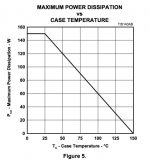
Can you touch the heatsinks now? I'm really not sure one pair of BDW83/84 will survive - case temperature will exceed 80C for sure. Maximum power derates heavily with temperature (see attached - this is BDW83), so at some point it's going to be dangerous. The temperature will keep rising, the SOA will keep falling.
With 10KHz square wave and 2.2uF in parallel with the load it will die at much lower power, as Sakis just mentioned. I ran such a test with OPS, equipped with 3 pairs MT-200 Sankens, 20V p-p, but it was already a very hard run - big heatsink got slightly above 90C and finally 2.2uF capacitor's copper lead has melted, decreasing the load 😱
But don't compare 3 pairs of MT-200s with 1 pair of BDW83/84, whatever package the've got (there are many options). In the other situation with the faulty front-end and the same OPS I've got a nasty high-swing oscillation for a few seconds, resulting in power black-out for the whole apartment. OPS became hot, but survived...
Sakis is right, these parts are obsolete - some datasheets indicate "1978, revised in 1997", it's not in production any more.
Attachments
Won´t argue about BDW93/94 because their small TO220 cases and inherent high thermal resistance won´t let them dissipate anything like what´s needed here for safe use, but TO218/247 TIP142/147 are rugged beasts, and the industry standard in 60 to 120W Guitar and Bass amplifiers (with one example, Fender Stage 160 reaching 160W RMS) , they are the most used transistors in Fender, Peavey, Marshall, Crate, Ampeg, Hughes & Kettner, many Laney ... and lots others (including my own 😉 )There is no point to argue about this ...Just look at the market ...if your sayings are correct other designers or manufacturers could use them also THEY DONT ....
Remember Musical Instrument use is the worst of them all, because amplifiers are ROUTINELY overdriven, transported, plugged in-out all the time, sometimes extra cabinets are added "just for kicks" , crude guitar and bass cabinets have terrible impedance curves, the works.
Just as examples here there are a Marshall 100W@4 ohms amplifier, originally with BDV64/65 but then fitted with TIP142/147 .
Fender Deluxe 112 (one of dozens):
An externally hosted image should be here but it was not working when we last tested it.
Hughes & Kettner Vortex . Like most others in its class, 80W@8 ohms and 100/120W into 4 ohms.
An externally hosted image should be here but it was not working when we last tested it.
These are the only ones using 120pF BC caps; all others work happily without them.
Mr V, I have never used or mentioned BDW83/84.
As I said in a previous post, running a pure sine wave 85W 1 pair of 2SA1943 / 2SC5200 will be pushing the limits. I don't have a 300 W dummy load to test >30V peak square wave, nor do I listen to square waves. Frankly they don't sound nice and tend to destroy tweeters. I listen to music which has dynamic range.
Mr Sakis, do you know what a miller cap is? BC cap in output stage is not a miller cap. For one thing, gain of a class AB stage is 1. My VAS gain is huge, thus 150pF works well. Larger and the input capacitance is too much.
I'll be. BDW93C Fairchild is in stock @ newark (farnell USA) for $.92 each. TO-220 though. Also stocked are multicomp and ST brands for a little more money.
I'm already using TIP142 darlingtons in TO3-P for voltage regulators. 5 in parallel for 12 amps 10 v drop. I'm more conservative with $1 parts than Mr. cloc. The emitter resistors cost half of that.
Thanks to Mr Fahey for the state of the art TIP142/147 schematics from the guitar world. Fortunately in that world designers know exactly what their speaker impedance is, since it is packaged in the amp with the driver board.
Wattage ratings thrown around here tend to be one hour ratings, not the 10 second ratings advertised on E-bay. Too late to change Mrcloc's thread title even though his amp has 1 pair output transistors. I'm trying to get 200 W peak 8 ohm out of a single pair NTE60 (white box Mj802? ) but classical music is very peaky - 1/2 W is my average listening level. I have some 50+ db peak to intro LP's (1812 overture Mercury Living Presence) and hoping for 70 db CD's some day.
When I tried to use that single pair output transistor amp for PA service for my keyboard, maybe 10 W/ch, I melted solder after 3.5 hours. The OT's survived but the driver board went up in flame. I was driving Peavey 1210 speakers, the channel that melted may have a 4 ohm driver in it instead of specified 8 ohm. Speaker measures 5.5 ohm with DVM. I've got a 10 pair MJ15024/25 PV-1.3k amp for keyboard service now - with a 8" fan. I was looking to buy a PV4 but instead found this $55 burned hulk rated 360 w/ch 8 ohms.
Last edited:
MArvelous ...
in hifi application though things are not the same regarding compensation at least a standard practice
Though to be honest with you the schematics you posted need some evaluation before put in comparison with a hifi circuit ...
One has to calculate the bandwidth of the amplifier then calculate exactly where the Vi limiter cuts in
similar for the second and see where exactly the diodes shunt the drive and the bandwidth
and as about the third schematic that also proved exactly what i said that a transistor of that beta cannot be left on its own and requires protection with a Vi limmiter diodes and or miller caps
Finally in the total picture you are missing that units like that operate in far easier conditions IE just one speaker unit no crossover and a very short cable . Often also these amplifier do not have to handle the all spectra since the play for only guitars which will mean mostly middle and high and less bass or the opposite plenty of bass bit of middle and no high at all
So comparison is not the same at all
And obviously in none of the schematics you will find 0.1 ballast resistors .....
Last edited:
you can't be serious about this ....
In alldatasheet.com that exist a number of datasheet published from trusted manufacturers and you expect me to trust a what ever site ?
Sorry this is not the way i do things the first thing i will look is the original manufacturer datasheet ...
In alldatasheet.com that exist a number of datasheet published from trusted manufacturers and you expect me to trust a what ever site ?
Sorry this is not the way i do things the first thing i will look is the original manufacturer datasheet ...
I agree, but the spec at the vendor agreed. Anyway, I'll get that video of results as soon as i can.
- Status
- Not open for further replies.
- Home
- Amplifiers
- Solid State
- New design 135W 8, 270W 4