The only european design transistors I've bought from major distributors were BC557 (pnp to92) and BC639 (npn to92) from ON semi via farnell, BD139 and BD140 (TO126) from fairchild via farnell, the 139/140 are specified to not meet the Phillips Ft spec.
Japanese transistors are even worse. I got 2sc3423 npn from farnell, advertised as being toshiba but came in with Y for a logo. They don't have a metal heat tab, it is plastic, so not suitable for heat sensing. $1.38 each. I got 2SA1837 pnp from digikey; they issued a toshiba datasheet but actually they have a 5:Z as the logo. The latter don't have a metal heat tab either, not suitable for heat sensing. $.72 each.
I can get real ON semi stuff including MJE15032/33 but they are $4 each. 30 mhz Ft, not as fast as the mythical Japanese VAS and Vbe multiplier parts. TIP31/32C and TIP41/42C are real and $.40 but slow at 3 mhz Ft. All you e-bay fans, I'm not interested, I can't test for Ft and can't tell real from fake VAS parts. I'm just barely capable of testing Vceo - I measure Ic at 12 or 48 VDC with emitter open.
I can get all the TO3P NJW1302 and NJL4281, NJW21194 & MJL21195 I want for $3 to 4, so I won't have to do the 10 parallel TIP41C dodge you will have to do in South Africa on the output stage. One pair can do 60 W steady 8 ohm maybe 200W peak single cannon shot on 72 v power supply.
The cool thing about the Panasonic SU380 or Apex AX6, they can be quasi-comp output so a single supply can be used with a 3300 uf capacitor between the O.T.'s and the speakers. One solder joint lets go, a split supply amp your transistors overheat, short, and could blow your speaker. This is diyaudio, my solder joints aren't done by a wave machine or trained operators either. My speakers are ~$350 used and $620 new, so I really don't want to blow them. 2n5401/5551 should take a 72 v rail and not blow up on the input stage. And I can buy those all day.
The downside of SU380 or AX6, the input resistance is maybe 47 kohm, way to low to be compatible with my PAS2 preamp. The dynaco ST120 input stage which is 500k input resistance used a specified gain transistor BC108c which I can't buy anymore.
Last edited:
I'm resurrecting this one because after years of design and experimenting, I've found a design which does very well, and I will use this design for my amplifiers in the future (modified for >100W).
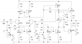
I've built this amplifier for 30W in 4 ohms, leaving out the current mirror on the collectors of the LTP. I will have to measure it properly, but it works as designed. Lovely to set up - bias current increases very slowly in the range you want it. For lower power, I use smaller zeners (I actually used 2 series LEDs giving 1.4V in the 30W version).
Ideally, Q11 and Q12 must be thermally connected, as must Q3 and Q4. Q5 and Q6 must most definitely be thermally connected. BC639's and BC640's will also work well for these transistors. I believe you can use a BD140 in the place of Q10. Q7 must be thermally connected to the outputs.
R11 and R12 are a 2k 10 turn pot.
R8 ~= (|Vcc|-Vz)/4 [kOhm]
R1 ~= (|Vcc|-Vz)/6 [kOhm]
The zeners can get a little noisy (not too bad to my ears), but I think they can have a 100nF in parallel if noise is an issue. Ideally 0.5W metal film resistors must be used. I used 0.25W carbon resistors, and noise is quite high. Still acceptable for the purpose of the amp, but unacceptable for proper hifi. R18 can be 22kOhm - 39kOhm, depending on the gain required (use one standard value higher for R9).
For 100W, I recommend TIP142/TIP147.
As shown, the amplifier uses a 25-0-25 transformer and will do 70W in 8 ohms, it just needs a big heatsink. Bias is set to about 80 mA for the simulation, but 10 mA will still be fine in practice.
Simulated THD is about 0.0005% (better than -106 dB for any harmonic). PSRR is theoretically about -61 dB.
Attachments
I'm resurrecting this one because after years of design and experimenting, I've found a design which does very well, and I will use this design for my amplifiers in the future (modified for >100W).
I've built this amplifier for 30W in 4 ohms, leaving out the current mirror on the collectors of the LTP. I will have to measure it properly, but it works as designed. Lovely to set up - bias current increases very slowly in the range you want it. For lower power, I use smaller zeners (I actually used 2 series LEDs giving 1.4V in the 30W version).
Ideally, Q11 and Q12 must be thermally connected, as must Q3 and Q4. Q5 and Q6 must most definitely be thermally connected. BC639's and BC640's will also work well for these transistors. I believe you can use a BD140 in the place of Q10. Q7 must be thermally connected to the outputs.
R11 and R12 are a 2k 10 turn pot.
R8 ~= (|Vcc|-Vz)/4 [kOhm]
R1 ~= (|Vcc|-Vz)/6 [kOhm]
The zeners can get a little noisy (not too bad to my ears), but I think they can have a 100nF in parallel if noise is an issue. Ideally 0.5W metal film resistors must be used. I used 0.25W carbon resistors, and noise is quite high. Still acceptable for the purpose of the amp, but unacceptable for proper hifi. R18 can be 22kOhm - 39kOhm, depending on the gain required (use one standard value higher for R9).
For 100W, I recommend TIP142/TIP147.
As shown, the amplifier uses a 25-0-25 transformer and will do 70W in 8 ohms, it just needs a big heatsink. Bias is set to about 80 mA for the simulation, but 10 mA will still be fine in practice.
Simulated THD is about 0.0005% (better than -106 dB for any harmonic). PSRR is theoretically about -61 dB.
You cannot be serious about this .....
for a number of reasons ...
---Title of 135-270W doesn't match and that can be very misleading...
---You cannot design amplifier now days with parts of unknown cob or ft (for tip 142-147 )
Darlington of that era are made for switching applications with low pitch linearity is pretty suspect ft is unknown ....
Darlington are notorious for thermal stability problems and since beta is extremely high for a single active device and you will never find a design that uses this type of semis and feature 0.1R emitter resistors ( ballast resistors are to be of the 0.68 to be able to balance the output semis )
Even the bigger brothers like SAP15 already including in the body thermal tracking devices in real life fail with no obvious reasons
BDW83 are obsolete and in general none of these devices is used today in audio amplifiers ....for the above and more reasons
remember that your simulator thinks that all these semis are perfect and that is why you produce so nice simulated results ...In real life this circuit will be able to work up to 30+30V and produce a few watt of crappy sound ....anything above that will eventually fail as all cousins and brothers failed in the past ....
Smoky regards
Sakis
And the VAS (Q10) forces the mirror to operate with only 600 to 700mV across {Q12+R15}
2n5401 are terrible at this duty.
You need far more than 700mV to get the mirror to work properly.
Q3 and Q6 suffer a similar "wrong transistor" for this duty.
2n5401 are terrible at this duty.
You need far more than 700mV to get the mirror to work properly.
Q3 and Q6 suffer a similar "wrong transistor" for this duty.
Last edited:
remember that your simulator thinks that all these semis are perfect and that is why you produce so nice simulated results ...In real life this circuit will be able to work up to 30+30V and produce a few watt of crappy sound ....anything above that will eventually fail as all cousins and brothers failed in the past ....
Smoky regards
Sakis
Ok, I value the insight.
I built the prototype with +-43 V, and it's being abused since. No thermal issues. The BDW93/94's are nice transistors. The prototype is getting 90W with no issues. The heatsinks get warm and then settle down nicely again when the music stops. I designed the amplifier here based on that prototype. The simulation is a reflection of my physical tinkering with the prototype and the initial circuit I built for the 30W version I speak about. And in the prototype the bias transistor isn't thermally connected to the outputs.
I have 2 old 100W amplifiers using TIP142/7 with no thermal issues - they've been in heavy home use as well as PA use for years.
--
Andrew, the 2N5401's are linear from about 0.35 V (Vce). Their saturation characteristics make them particularly good in current mirrors. Anyway, these should probably be BC556's.
--
WRT the title - this amplifier will be able to get to 135 W with careful considerations of the output devices. 270 W will probably be a stretch. But this amplifier is a continuation of what I learned with my initial posting: The symmetrical design was something I did (physically; not in simulations), and then found I needed to sort out the thermal issues. Based on that, I came to the design in my first post. Since then, I've ironed out stability issues, and moved away from the symmetrical design because it has no advantage. I would need to consider the thermal implications of >100 W with this design, which I haven't done yet. Also, I base my calculations for thermal stability, etc. on the premise that an 8 ohm speaker isn't 8 ohms, but will often vary from 3 to 10 ohms.
The only european design transistors I've bought from major distributors were BC557 (pnp to92) and BC639 (npn to92) from ON semi via farnell, BD139 and BD140 (TO126) from fairchild via farnell, the 139/140 are specified to not meet the Phillips Ft spec.
Japanese transistors are even worse. I got 2sc3423 npn from farnell, advertised as being toshiba but came in with Y for a logo. They don't have a metal heat tab, it is plastic, so not suitable for heat sensing. $1.38 each. I got 2SA1837 pnp from digikey; they issued a toshiba datasheet but actually they have a 5:Z as the logo. The latter don't have a metal heat tab either, not suitable for heat sensing. $.72 each.
I can get real ON semi stuff including MJE15032/33 but they are $4 each. 30 mhz Ft, not as fast as the mythical Japanese VAS and Vbe multiplier parts. TIP31/32C and TIP41/42C are real and $.40 but slow at 3 mhz Ft. All you e-bay fans, I'm not interested, I can't test for Ft and can't tell real from fake VAS parts. I'm just barely capable of testing Vceo - I measure Ic at 12 or 48 VDC with emitter open.
I can get all the TO3P NJW1302 and NJL4281, NJW21194 & MJL21195 I want for $3 to 4, so I won't have to do the 10 parallel TIP41C dodge you will have to do in South Africa on the output stage. One pair can do 60 W steady 8 ohm maybe 200W peak single cannon shot on 72 v power supply.
The cool thing about the Panasonic SU380 or Apex AX6, they can be quasi-comp output so a single supply can be used with a 3300 uf capacitor between the O.T.'s and the speakers. One solder joint lets go, a split supply amp your transistors overheat, short, and could blow your speaker. This is diyaudio, my solder joints aren't done by a wave machine or trained operators either. My speakers are ~$350 used and $620 new, so I really don't want to blow them. 2n5401/5551 should take a 72 v rail and not blow up on the input stage. And I can buy those all day.
The downside of SU380 or AX6, the input resistance is maybe 47 kohm, way to low to be compatible with my PAS2 preamp. The dynaco ST120 input stage which is 500k input resistance used a specified gain transistor BC108c which I can't buy anymore.
Many small power transistors are encased in epoxy nowadays and just because a metal tab is not exposed doesn't mean they can't be used for temperature compensation Vbe multiplier. Most BD139's now are encased but have a small metal contact exposed on the back. But epoxy conducts heat quite well and besides, a small thermal time constant to smooth things out for stability of the bias current isn't a bad thing.
Ok, I value the insight.
I built the prototype with +-43 V, and it's being abused since. No thermal issues. The BDW93/94's are nice transistors. The prototype is getting 90W with no issues. The heatsinks get warm and then settle down nicely again when the music stops. I designed the amplifier here based on that prototype. The simulation is a reflection of my physical tinkering with the prototype and the initial circuit I built for the 30W version I speak about. And in the prototype the bias transistor isn't thermally connected to the outputs.
I have 2 old 100W amplifiers using TIP142/7 with no thermal issues - they've been in heavy home use as well as PA use for years.
--
Andrew, the 2N5401's are linear from about 0.35 V (Vce). Their saturation characteristics make them particularly good in current mirrors. Anyway, these should probably be BC556's.
--
WRT the title - this amplifier will be able to get to 135 W with careful considerations of the output devices. 270 W will probably be a stretch. But this amplifier is a continuation of what I learned with my initial posting: The symmetrical design was something I did (physically; not in simulations), and then found I needed to sort out the thermal issues. Based on that, I came to the design in my first post. Since then, I've ironed out stability issues, and moved away from the symmetrical design because it has no advantage. I would need to consider the thermal implications of >100 W with this design, which I haven't done yet. Also, I base my calculations for thermal stability, etc. on the premise that an 8 ohm speaker isn't 8 ohms, but will often vary from 3 to 10 ohms.
There is no point to argue about this ...Just look at the market ...if your sayings are correct other designers or manufacturers could use them also THEY DONT ....
There is no point to argue about this ...Just look at the market ...if your sayings are correct other designers or manufacturers could use them also THEY DONT ....
No - they use chips for this sort of power...
I'd take Mr. East's advice at least to replace the .1 resistors with .51 ohm resistors - and on the emitters, not on the collector of the bottom one. On the emitter it cuts the gain when the output transistor heats up. So the theory goes from .00005 % HD to .001% HD. You'll never hear the difference on a speaker.
I've solved my 100 k input impedance problem without actually using your darlington input of the original. Remember I need >250k input impedance to be compatible with a 12AX7 preamp driver. In tryng to to put the idle point of the AX6 in the middle of the 72 v power supply the impedance goes up. The On Semi brand 2n5401 input transistor was pulling the collector down to 6 v with the suggested 270k pullup on the base and a 100k pulldown. So I've got the pulldown resistor up to 390k and it is still idling cold at 28v collector. 470k pullup and pulldown will be my next try next rainy day- giving about 250 k input inpedance.
Who knows what the idle point will go to when it heats up? It matters on a single supply amp, having the output to the speaker capacitor in the middle of the PS cuts the 2nd harmonic distortion.
All these European part numbers are totally impossible to buy here from genuine distributors. Only the E-bay vendors stock them, and most of those will probably be something else with new paint logos.
I like MJ150xxG output transistors. Made in Mexico, genuine from farnell mouser or digikey, always in stock, lots of gain. MJE150xx TO220 drivers have lots of gain too, so I don't need a darlington output transistor. Just a cheap old TIP41C or GE D44-R2 as VAS.
Last edited:
no ...they use real semis ...
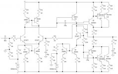
175W 8 ohm, theoretically. +-57V supply. Choose your output's.
For my purposes and the power range I expect to output, the BDW94/3's are perfect. Like I said, I've used them to good effect already. If more power is needed, the output stage can be changed, it's no big deal.
Usually in the 15 W to 70 W region, class D is used because it's cheap. But it doesn't sound good. I have yet to hear a good sounding class D amplifier. With my Darlington output, I get the quality I want, and it's a bit more convenient. Absolutely no problem changing out the Darlington monolithics for a CFP.
Attachments
I'd take Mr. East's advice at least to replace the .1 resistors with .51 ohm resistors - and on the emitters, not on the collector of the bottom one. On the emitter it cuts the gain when the output transistor heats up. So the theory goes from .00005 % HD to .001% HD. You'll never hear the difference on a speaker.
I've solved my 100 k input impedance problem without actually using your darlington input of the original. Remember I need >250k input impedance to be compatible with a 12AX7 preamp driver. In tryng to to put the idle point of the AX6 in the middle of the 72 v power supply the impedance goes up. The On Semi brand 2n5401 input transistor was pulling the collector down to 6 v with the suggested 270k pullup on the base and a 100k pulldown. So I've got the pulldown resistor up to 390k and it is still idling cold at 28v collector. 470k pullup and pulldown will be my next try next rainy day- giving about 250 k input inpedance.
Who knows what the idle point will go to when it heats up? It matters on a single supply amp, having the output to the speaker capacitor in the middle of the PS cuts the 2nd harmonic distortion.
All these European part numbers are totally impossible to buy here from genuine distributors. Only the E-bay vendors stock them, and most of those will probably be something else with new paint logos.
I like MJ150xxG output transistors. Made in Mexico, genuine from farnell mouser or digikey, always in stock, lots of gain. MJE150xx TO220 drivers have lots of gain too, so I don't need a darlington output transistor. Just a cheap old TIP41C or GE D44-R2 as VAS.
Hi Indianajo
I honestly would build a buffer to interface your preamp and power amp. You can use a Darlington LTP powered from your 72V, no problem. It will be easier than building an amplifier which isn't fully tested. And usually you only need transistors which can handle the voltage. It's not difficult to find suitable transistors. Let me know if you want a buffer design.
I consider that to be the opposite to what the thermal compensation should be doing.Many small power transistors are encased in epoxy nowadays and just because a metal tab is not exposed doesn't mean they can't be used for temperature compensation Vbe multiplier. Most BD139's now are encased but have a small metal contact exposed on the back. But epoxy conducts heat quite well and besides, a small thermal time constant to smooth things out for stability of the bias current isn't a bad thing.
The compensator should be monitoring the junction temperature of the output devices and the faster they can follow the Tj chnages the better the tempco can do it's job.
It's no good waiting for a minute to read a portion of the Tj change and then apply a multiplication factor to compensate for the full Tj change and make that compensation AFTER the output stage has passed it's high temperature event.
D.Self and R.Cordell have discussed this at length. Sanken and Onsemi have devices manufactured to minimise the sensor delay.
Another whole transformer with center tap involves a purchase from Ch*** which I don't do. I'll try to make do with the tranformers I have.
If you want to dump the darlingtons and stay with TO92 drivers, On Semi MPSW55 and 56 have 1 W dissipation instead of 650 mw of 2n5401/5550. There are some Japanese transistors in very tall TO92 derivative packages for higher power dissipation too. I've seen them in switcher power supplies, but never complimentary pairs. And Zetex made some TO92 for drivers with little heat tabs and 1 w dissipation for Allen organ, 2n6715 npn and 2n6727 pnp.
If you want to dump the darlingtons and stay with TO92 drivers, On Semi MPSW55 and 56 have 1 W dissipation instead of 650 mw of 2n5401/5550. There are some Japanese transistors in very tall TO92 derivative packages for higher power dissipation too. I've seen them in switcher power supplies, but never complimentary pairs. And Zetex made some TO92 for drivers with little heat tabs and 1 w dissipation for Allen organ, 2n6715 npn and 2n6727 pnp.
In addition to the mod I posted, those Darlingtons make excellent drivers. I'll post a schematic sometime.
Another whole transformer with center tap involves a purchase from Ch*** which I don't do. I'll try to make do with the tranformers I have.
If you want to dump the darlingtons and stay with TO92 drivers, On Semi MPSW55 and 56 have 1 W dissipation instead of 650 mw of 2n5401/5550. There are some Japanese transistors in very tall TO92 derivative packages for higher power dissipation too. I've seen them in switcher power supplies, but never complimentary pairs. And Zetex made some TO92 for drivers with little heat tabs and 1 w dissipation for Allen organ, 2n6715 npn and 2n6727 pnp.
Hi. I don't have much of a selection here. The Darlingtons make nice output transistors for lower power. For higher power, a small modification can give excellent results. I'll post it soon. The only problem I have with TO92 transistors is that you can't stabilize them thermally very easily.
Anyway, I'll post a buffer design for you to show >100k input impedance, and will run off your current positive voltage (I'll make it run off 30 - 150 V or something like that). I'll try post sometime today. 🙂 A few resistors and transistors, low power, maybe a diode or two.
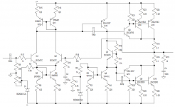
With careful consideration of the output devices, here is a modification for 135 W / 270 W for 8 ohm / 4 ohm respectively. For this to drive 8 ohms, you only need one pair of power transistors, and they can both be mounted on a 0.6 K/W heatsink. To drive 4 ohms, both output pairs are needed, and two output transistors must be mounted on a 0.6 K/W heatsink at least.
The nice thing here is that because of the high beta of the Darlingtons, the VAS stage current can still be around 4 mA, and the power stage can be driven fully. The Darlingtons must be thermally connected to Q7. Q5 and Q6 must be the same, and I suspect a TO126 transistor will be better here - mount them one on top of the other on a small heatsink. Q10 will also do well as a TO126/TO220 transistor mounted on a small heatsink.
The nice thing here is that because of the high beta of the Darlingtons, the VAS stage current can still be around 4 mA, and the power stage can be driven fully. The Darlingtons must be thermally connected to Q7. Q5 and Q6 must be the same, and I suspect a TO126 transistor will be better here - mount them one on top of the other on a small heatsink. Q10 will also do well as a TO126/TO220 transistor mounted on a small heatsink.
Attachments
- Status
- Not open for further replies.
- Home
- Amplifiers
- Solid State
- New design 135W 8, 270W 4