I updated the simulation with your box volumes for the mid and woofer (be careful with stuffing because it will act as further increase of the volume).
I went with a 7 cm inner diameter of the port since 3 inch ports are common and I usually use a piece of drain pipe with a 7 cm inner diameter (cheap and common where I live).
Mid:
I went with a 7 cm inner diameter of the port since 3 inch ports are common and I usually use a piece of drain pipe with a 7 cm inner diameter (cheap and common where I live).
Mid:
- Box volume Vb=13.3 l
- Total Q factor Qtc=0.69
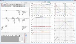
- Box volume Vb = 54.5 l
- Vent diameter and length Dv=7.0 cm, Lv=20.4 cm
- f3 = 32.2 Hz
Attachments
Thankyou I really appreciate what you have done with it.
I could try making it but just looked online here in Australia on the biggest store I know of wagnerelectronics there seemed to be so many different types of capacitors I got a little lost. I might have order the parts for them from overseas if I was to go ahead
Here is the speaker layout I was planning ignore the cutouts. The human voice frequencies which is the major component of the music would not be coming from the tweeter so I could not understand why that would be placed at ear height? What do you think?


The recess all the way around the edges of the cabinet face will be 20mm inset now not 30 as I've had to cut a new peice of 9 mm OSB board and will fill the old cut outs (I originally had 4x SB 6.5"s)
I put the recess to help prevent my pet birds messing on the driver cones. Although now it is uneccesary because I have purchased these bird spikes to put on top of the speakers (I know it will look bad). I'm thinking perhaps I should not do this recess at all if it will interfere with the acoustics?
They dive bomb my speakers!!!
It penetrates through the fabric on to the driver.


What are the arrows on the schematic of the crossover design.
Regards Tim
I could try making it but just looked online here in Australia on the biggest store I know of wagnerelectronics there seemed to be so many different types of capacitors I got a little lost. I might have order the parts for them from overseas if I was to go ahead
Here is the speaker layout I was planning ignore the cutouts. The human voice frequencies which is the major component of the music would not be coming from the tweeter so I could not understand why that would be placed at ear height? What do you think?
The recess all the way around the edges of the cabinet face will be 20mm inset now not 30 as I've had to cut a new peice of 9 mm OSB board and will fill the old cut outs (I originally had 4x SB 6.5"s)
I put the recess to help prevent my pet birds messing on the driver cones. Although now it is uneccesary because I have purchased these bird spikes to put on top of the speakers (I know it will look bad). I'm thinking perhaps I should not do this recess at all if it will interfere with the acoustics?
They dive bomb my speakers!!!
It penetrates through the fabric on to the driver.
What are the arrows on the schematic of the crossover design.
Regards Tim
Last edited:
Great because that is what I simulated but I got a bit confused by the photo of the baffle, it seems to have six holes but I think I get it now. Its going to get a new baffle and the speaker grills mark where you plan to put the drivers, right? From top to bottom - mid, tweeter, woofer, right?Hi ☺️
I have one 6.5" and one 10" in each box and one port.
Regards Tim
Yes that's it, your correct, actually I've already repaired all the old speaker holes with lots of circles and epoxy.
I'll fill the inside of my 70mm PVC downpipe for the ports with epoxy fiberglass to get down it to 68 mm as I have no room left to make it 54 litres.
I'll fill the inside of my 70mm PVC downpipe for the ports with epoxy fiberglass to get down it to 68 mm as I have no room left to make it 54 litres.
Last edited:
Just changing a driver from an 8Ω version to a 4Ω version will shift filter corner frequencies by an octave up or down (doubling or halving); the same for doubling up with drivers..
I'm sorry, but this is incorrect. The shift of the impedance will change the Q of the xover, not the Fc. The only way this is valid as to shifting in half or double due to the impedance change is for 1st order xovers.
While the change in Q will affect the response to where drivers rolloff differently than at the other Q, the Fc of the components in the xover (or the resonance of the components) will not actually change.
Best regards,
Wolf
Note: My last simulation got a woofer box volume of 54.5 litres and a port with an inner diameter of 70mm (because I guessed you would use a 3 inch port). The port length in that simulation is: 20.4 cm.I'll fill the inside of my 70mm PVC downpipe for the ports with epoxy fiberglass to get down it to 68 mm as I have no room left to make it 54 litres.
Yes that's right, I do have the 3" pipe, but my box is only 23 cm from front to back the port will need to take a 90 degree turn or alternatively I can put it on side of cabinet to keep it straight as box is 34cm wide. I don't mind reducing it from 70 mm to 68 shouldn't be too difficult.
Tim
Tim
It doesn't have to be 90 degrees, I sometimes use a 45 degrees elbow PVC pipe fitting, its better than 90 degrees. You can run the ports from the side, its probably better than not having enough distance to the back.Yes that's right, I do have the 3" pipe, but my box is only 23 cm from front to back the port will need to take a 90 degree turn or alternatively I can put it on side of cabinet to keep it straight as box is 34cm wide. I don't mind reducing it from 70 mm to 68 shouldn't be too difficult.
Tim
Alternatively I have four 2 inch ports coming in the mail, I could use them but when I did the calcs for them I think they had to be longer than a single.
I like the appearance of a port with the curved recess at the front.
I like the appearance of a port with the curved recess at the front.
Last edited:
Where you put the port doesn't matter much as long as the exit stays clear from adjacent objects (like walls and furniture). If you like the look of it on the front and lack distance to the back, then just go with a 45-degrees elbow pipe fitting close to the back side of the baffle and direct the port diagonally where there is room. Just stay clear from any inner walls.I like the appearance of a port with the curved recess at the front.
Bends in ports don't really work because of de-lamination of the airflow and susequent turbulence. Does the simulation allow for flared ends on the port which shortens the length needed? Has the length available been measured from the front of the baffle?
I actually wish airflow de-lamination was our biggest issue... 😀Bends in ports don't really work ...
This link on port testing with flares and different sizes is interesting . I wanted to do a flared port 150 front by 70 back by 50 mm deep but the calculations are too difficult for me to work out.
Port Flares - Evaluation of noise
It would look something like this in pic with the edges of my OSB board rolled back and exposed. It's too complex for me to do the math on and I'd still need a 45 degree bend in the port.


Port Flares - Evaluation of noise
It would look something like this in pic with the edges of my OSB board rolled back and exposed. It's too complex for me to do the math on and I'd still need a 45 degree bend in the port.
Last edited:
Troels also got a really nice write-up on vent tuning of ported systems (and calculations): vent tuningThis link on port testing with flares and different sizes is interesting ...
Like I said before, i prefer the sound of sealed enclosures so I have never worried much about port flairs and such. Airflow de-lamination might be a problem, how much of a problem? I don't know. If I ever build anything with a port I flair the end facing outside (with a round-over router bit, as much for esthetics as for sonics) and I keep the other end free. Have you considered a slot port? Easy enough to get almost any length even if depth of the box is limited. Long ones often bend 90 degrees, sometimes more than once. Makes me wonder if airflow de-lamination is applicable to slot ports or not, and if not why? 😕
Last edited:
Airflow becomes turbulent on mechanical impedance changes, like bends in a tube or un-flared tube ends. Air turbulence makes reflex tuning ports even more non-linear than than they are naturally. Flares reduce terminal air velocity and increase the apparent length of the port by coupling more mass of air external to the port.
It's very easy to demonstrate port noise; just play a sine wave tone at the port tuning frequency and you'll be chuffed (pun intended!) Even a 1mm radius on the inside of the tube ends will significantly reduce air turbulence and noise at port exits. A deburring tool is a quick and simple way to radius a PVC tube. Note sliding ports or tubes with seams in them are usually pretty bad. If a port is made of sections it is imperative that there is no surface irregularity at the joins. If you can feel the joint with your finger, then it's likely a problem.
It's very easy to demonstrate port noise; just play a sine wave tone at the port tuning frequency and you'll be chuffed (pun intended!) Even a 1mm radius on the inside of the tube ends will significantly reduce air turbulence and noise at port exits. A deburring tool is a quick and simple way to radius a PVC tube. Note sliding ports or tubes with seams in them are usually pretty bad. If a port is made of sections it is imperative that there is no surface irregularity at the joins. If you can feel the joint with your finger, then it's likely a problem.
I don't doubt you, its the laws of physics (like everything else speakers). I personally don't know how critical it is and how much of an impact a 45 degrees bend on a 70 mm port might be? To me a port is just a plug of air acting as a resonator. I do understand that the plug will be affected by the space it is moving in but I cant visualize the magnitude compared to everything else involved. Conceptually it doesn't really matter, you should try to get as much right as possible (even if the magnitude is small because things tend to add up), I agree with you on that. And this is, IMHO, another good reason to stay away from ported designs since a sealed is pretty forgiving and comparable easy to get right.Airflow becomes turbulent on mechanical impedance changes ...
The best analogy I can think of for port behaviour is a ball connected to a paddle by a rubber string, with the paddle being the speaker cone, the ball the port air mass, and the string the effective air compliance of the box and driver. Well below resonance the paddle and the ball move together staying equidistant (although in a speaker system the two are out of phase), well above resonance the ball doesn't move no matter what the paddle displacement, at resonance the ball displacement is at maximum even though the paddle is barely moving.
Now imagine that at resonance the ball has to bend through a curve for each stoke of oscillation because it is constrained by a mechanical guide. Bummer.
Now imagine that at resonance the ball has to bend through a curve for each stoke of oscillation because it is constrained by a mechanical guide. Bummer.
- Home
- Loudspeakers
- Multi-Way
- New Crossovers with Hz/db switches & DIY speakers