It is the crossover and driver characteristics (impedance vs frequency and output & phase vs frequency) together that determine crossover frequencies. Specifying crossover frequencies for a crossover is somewhat meaningless without the data for the drivers that terminate each section of the crossover. Just changing a driver from an 8Ω version to a 4Ω version will shift filter corner frequencies by an octave up or down (doubling or halving); the same for doubling up with drivers.
The different sensitivities and physical distance offsets of the drivers as mounted on the box also need to be taken into account to align the crossover. If measured properly this sensitivity and relative phase data is embedded in the FRD file for each driver created by the OmniMic system.
The program that I used to draw the crossover is XSim. If the impedance data for each driver is measured with a system like Dayton's DATS, and the phase/frequency response as mounted on the cabinet is measured with a system like Dayton's OmniMic, it is possible to create data files for each driver that can be imported into XSim, and then that program will show you what the crossover frequencies are as you adjust the values of components for the crossover.
The ScanSpeak is fine, however the SBs have a wider bandwidth and might be a better choice. I can't comment on sound differences between them.
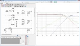
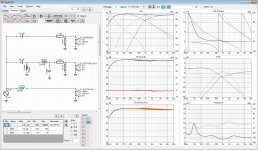
Mine looked almost the same but I could not read the inductor values. Here is my simulation in VituixCAD. There are no switches in VituixCAD but you can open or short any element. I have marked the wires I open and close representing the switches on the board. I used three generic drivers in this simulation, all set to 80 SPL and 8 Z. I have inverted driver #2 (the mid).I've attempted to draw out the crossover. Please feel free to make corrections.
Image 1 is with all switches open (it seems to be the default based on images of the board). The bass seems to be down -0.3 dB to start with and I get F3 to be around 1743 Hz. The tweeter is down -1.3 dB with an F3 of around 5800 Hz. The mid is down -3.2 with F3s around 1230 Hz and 2830 Hz.
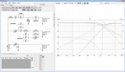
Image 2 is with the tweeters 0/3dB switch closed.
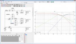
Image 3 is with the 0Hz/30Hz switch going to the three 1.5 uF capacitors closed.
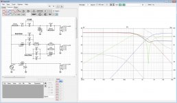
Image 4 is with the last 0Hz/30Hz switch going to the 3.3 uF capacitor closed.
Does any if this make any sense? And what about the switch going to the 3.3 uF capacitor, what is it for? Is this really the right component values (not that other values would help much)?
Attachments
Last edited:
Unfortunately the 1 mH and 4.7 uF for the Lowpass/Bass section is not even close for an 8 Ohms 10"woofer. This should in reality be in the 5 mH/80 uF ballpark.
The electrical sims in VCAD tell only half the story: load the real in box measurements (.frd and .zma files) of the drivers and it will get even worse. Sorry to say, but this x/o looks like a waste for such fine drivers.
The electrical sims in VCAD tell only half the story: load the real in box measurements (.frd and .zma files) of the drivers and it will get even worse. Sorry to say, but this x/o looks like a waste for such fine drivers.
Mine looked almost the same...
Does any if this make any sense? And what about the switch going to the 3.3 uF capacitor, what is it for? Is this really the right component values (not that other values would help much)?
Good to know I am not bonkers, but not sure about the person who designed this circuit...
Hi thanks all I really appreciate the input, I'll ditch it.
The only other crossover I could find that comes even close is this Kasun one at 3 times the price below in pic. Would this one work for my set is it enough for the 10".
There is also a 300w Dayton crossover called at XO3W-375/3K that crosses over low. Here is the Kasun it's at 650 and 2400 khz
I will a good look at your schematics tonight.
Tim
Last edited:
Originally Posted by EmuMannen View Post
Does any if this make any sense?
Some of it, problem is much of the incentive to learn it all is reduced because I am aware that even I went to the trouble to understand nearly all of it I could still easily miss one important factor and be not much better off. Possibly I'd still end up with the wrong crossover for the application. That's why smart people like you are on the forum.
Id prefer someone as experienced as you just say " here Tim use this one".
Can you see how many mistakes I've made on my speaker boxes re in pics. I think I've redone the calculations near 100 times.
I don't eknow what the Uf signature on the capacitor means or what they do. By F3 are you saying that it is close to where the ideal frequency range ends?
Tim

Last edited:
It was not directed towards you Tim. Passive crossovers are far from easy. But I would really like to have a chat with the guy who designed your crossover...Some of it, problem is much of the incentive to learn it all is reduced because I am aware that even I went to the trouble to understand nearly all of it I could still easily miss one important factor and be not much better off. Possibly I'd still end up with the wrong crossover for the application. That's why smart people like you are on the forum.
I know this is not what you want to here but it doesn't work that way. The only way to get it to work out of the box is to follow an already proven successful design. Anything else needs a lot of though, experience, calculations, measurements and tuning. You might have to do it in a couple of iterations to get it close to right and some combinations will never make it.Id prefer someone as experienced as you just say " here Tim use this one".
No because the boxes are just one piece of the puzzle. There are usually many rights and wrongs and a lot in between. Not referring to your boxes but generally speaking.Can you see how many mistakes I've made on my speaker boxes re in pics. I think I've redone the calculations near 100 times.
µF or uF is micro Farad, a way to quantify the main property of the component. It can be used as the high pass filter in a first order crossover or as part of a more complex higher order crossover.I don't eknow what the Uf signature on the capacitor means or what they do.
No I meant where the response is -3 dB down. A common way of specifying the crossover frequency.By F3 are you saying that it is close to where the ideal frequency range ends?
Last edited:
Ok Thanks
There is a professional speaker builder nearby, Arthur Francis perhaps he could make a crossover for me.
There is a professional speaker builder nearby, Arthur Francis perhaps he could make a crossover for me.
Last edited:
Sounds like a good idea but I am sure there are a lot of board members that can help you design a crossover for your speakers. But a lot of information is needed to get it right. The best input would be measurements for each driver (including ports and passive radiators if there are any). Far field, near field and impedance measurements with the elements mounted in your boxes.There is a professional speaker builder nearby, Arthur Francis perhaps he could make a crossover for me.
This would be "after the fact" of selecting drivers. You can therefor use free simulation software like VituixCAD or Basta! to simulate different drivers in different boxes and alignments if you need decision support selecting drivers or design your boxes.
So you do your design, pick your elements and build your boxes based on simulation. You can then use free measurement software like REW to measure the impedance and response of your drivers in your boxes (it should be close to the simulations but you need as accurate data as possible for the next stage). You then take the measured data and feed it to VituixCAD or other free software like Xsim to help you design your crossovers. You might have to iterate, remeasure, redesign, tweak and tune the crossovers until you are happy with the response.
You got a heads start if you got years of experience building speakers since you then know what will work or not, but the process is the same. There are no shortcuts, well maybe one, you could simulate everything without measuring. Trust the measurements by the manufacturer or others and the simulation software. You would probably end up with a pair of decent sounding speakers. Another option is to build an already proven design, that is the easiest and most bullet proof way of doing it but maybe not the most "incentive to learn" driven approach...
Ps. Note, the components for building just decent passive crossovers can be surprisingly expensive. I would budget at least $200 for a 3-way (second order, higher order would be more). That would be with budget components like Janzen Cross Cap and 0.8 mm air core inductors. Nothing special but good value for money.
Last edited:
Well ok, it seems I've underestimated whats involved.
The only thing I have to measure speakers with is a cheap battery powered 0 to 20 KHZ tester.
I know exact measurements of my speakers and compartments. I can post them latter.
I couldn't find any crossover's with 5 mH/80 uF for bass 10" woofer. Looks like it will have to be made.
The only thing I have to measure speakers with is a cheap battery powered 0 to 20 KHZ tester.
I know exact measurements of my speakers and compartments. I can post them latter.
I couldn't find any crossover's with 5 mH/80 uF for bass 10" woofer. Looks like it will have to be made.
So did I when I started out building speakers.Well ok, it seems I've underestimated whats involved.
I don't know if its usable, I personally use an old laptop with REW, a Steinberg UR22 Mk2 USB Audio Interface and a Line Audio Design OM1 as a measurement microphone. Pretty basic setup but really good value for money.The only thing I have to measure speakers with is a cheap battery powered 0 to 20 KHZ tester.
As drivers measured in your boxes and the volume of your boxes or manufacturers measurements (e.g. flush in infinite baffle, back side open (no cabinet) or IEC 268-5 baffle)? The former is preferred for accuracy, the latter can be used for simulation but it will only be as good as the simulation.I know exact measurements of my speakers and compartments. I can post them latter.
It is almost always better to custom build a crossover than to buy a generic one...I couldn't find any crossover's with 5 mH/80 uF for bass 10" woofer. Looks like it will have to be made.
You haven't bought the drivers yet, is that right? I think you got two options going forward. Either pick a good set of drivers based on the boxes you got. Or pick a good set of drivers and make the best possible boxes for them. You also have to decide if its going to be a closed design, ported, with passive radiators, transmission line or whatever. And that is just the beginning...
Yes I have purchased them the links to the data sheets for them are on page 2, also purchased a scanspeak 2606 tweeters
I didn't use the manufacturers specs for size enclose as it was off bass box 6 and seemed too small compaired to the calculator on this forum and Hodges. I can check when I get home but I ended up with approx 52 litres for ported for single 10" Dayton's and 13.2 for my SB 6.5"s each box.
Dayton RS270P-8A 10"
And the SB Acoustics SB17NRXC35-8 6.5"
Last edited:
OK so the current selection of drivers:Yes I have purchased them the links to the data sheets for them are on page 2...
- Tweeters: ScanSpeak D2606/922000
- Mids: SB Acoustics SB17NRXC35-8
- Woofers: Dayton Audio RS270P-8A
Last edited:
Yes that's all correct. I have the boxes built too except for the back all I can to add more volume is to put the back on instead cutting it in to insert in the back. I am over manufacturers recommendation by at least 20% as it based on diyaudio calculator.
I'll post the sizes exact sizes tomorrow
Regards
Tim
I'll post the sizes exact sizes tomorrow
Regards
Tim
Last edited:
OK here is my first stab at this, entirely built on manufacturer specifications and personal preferences so take it for what it is.
First we need to find out if the woofer is suitable for a sealed or a ported enclosure. So we calculate the Efficiency Bandwidth Product (EBP), it equals Free Air Resonance (Fs) / Driver Electrical "Q" (Qes) -> 22.9 / 0.42 = 54.5. Less than 50 calls for sealed, more than 90 calls for ported, anything between and we can go with either. We got EBP = 54.5 so we can go with either but I personally go for sealed whenever I can. I find them to sound better, they are easier and more predictable to get right and the bass can easily be extended with EQ.
You can do the same calculations for the mid if you want. The EBP = 88.9 but I don't even consider porting it when used as a mid.
I use the VituixCAD Enclosure Tool to figure out the volumes needed for the mid and the woofer where Qtc = 0.707 (critical dampening). This is what I get:
A lot of useful information but what I am looking for is the box volume (Vb) at total Q (Qtc) = 0.707
SB Acoustics SB17NRXC35-8 (sealed enclosure):
Something like the attached image as a starting point maybe? Someone else can probably do better. One drawback f3 = 52.6 Hz for a 10 inch woofer feels a bit on the high side. It can always be extended with a Linkwitz transform but it would have been nice with a lower f3. Maybe someone can come up with a ported alternative? A first order filter between woofer and mid would save some money. Maybe spend it on a third order filter between mid and tweeter?
Ps. there are a lot more to be done. I haven't simulated the baffle yet because I have no idea what you want the enclosures to look like, height, baffle width etc. It is needed to simulate baffle step loss and add it to the mix...
First we need to find out if the woofer is suitable for a sealed or a ported enclosure. So we calculate the Efficiency Bandwidth Product (EBP), it equals Free Air Resonance (Fs) / Driver Electrical "Q" (Qes) -> 22.9 / 0.42 = 54.5. Less than 50 calls for sealed, more than 90 calls for ported, anything between and we can go with either. We got EBP = 54.5 so we can go with either but I personally go for sealed whenever I can. I find them to sound better, they are easier and more predictable to get right and the bass can easily be extended with EQ.
You can do the same calculations for the mid if you want. The EBP = 88.9 but I don't even consider porting it when used as a mid.
I use the VituixCAD Enclosure Tool to figure out the volumes needed for the mid and the woofer where Qtc = 0.707 (critical dampening). This is what I get:
Code:
STATISTICS
 f3     70.3 Hz
 f6     53.4 Hz
 f10    40.6 Hz
 Zmin    5.7 Ohm @ 761.1 Hz
 Zmax   63.4 Ohm @ 68.3 Hz
 GDmax   3.9 ms  @ 45.6 Hz
 XmaxC     2 mm  @ 5 Hz
 Pmax    1.4 VA  @ 761.1 Hz
-------------------------------------------------------------
DRIVER: SB Acoustics SB17NRXC35-8, 1 pcs in series
 n0      0.39 %       Reference efficiency
 SPL     88.1 dB/W    Sensitivity
 USPL    89.5 dB/2.83 Sensitivity
 EBP     88.9         Efficiency bandwidth product
 Dd      12.3 cm      Effective diameter of driver
 Vd      64.9 cm^3    Maximum linear volume of displacement
 Cas  3.06E-7 m^5/N   Acoustic equivalent of Cms
 Mas    7.9E1 kg/m^4  Acoustic equivalent of Mms+Mme
 Ras   3.16E3 Ns/m^5  Acoustic equivalent of Rms
 Rae   4.39E4 Ns/m^5  Acoustic equivalent of Re+Rg
-------------------------------------------------------------
BOX REAR 1: Vb=12.4 l, Ql=100.0
 Fb      68.7 Hz      System resonance frequency
 Cab  8.74E-8 m^5/N   Acoustic compliance of air in enclosure
 Rab   8.84E2 Ns/m^5  Acoustic resistance due to absorption
 Ral   2.65E6 Ns/m^5  Acoustic resistance due to leakage
  Qtc     0.71         Total Q factor
Code:
STATISTICS
 f3     52.6 Hz
 f6       40 Hz
 f10    30.4 Hz
 Zmin    6.8 Ohm @ 39793.9 Hz
 Zmax   25.7 Ohm @ 52.6 Hz
 GDmax   5.1 ms  @ 35.1 Hz
 XmaxC     1 mm  @ 5 Hz
 Pmax    1.2 VA  @ 39793.9 Hz
-------------------------------------------------------------
DRIVER: Dayton Audio RS270P-8A, 1 pcs in series
 n0      0.31 %       Reference efficiency
 SPL     87.0 dB/W    Sensitivity
 USPL    87.7 dB/2.83 Sensitivity
 EBP     54.5         Efficiency bandwidth product
 Dd      21.0 cm      Effective diameter of driver
 Vd     207.8 cm^3    Maximum linear volume of displacement
 Cas  7.92E-7 m^5/N   Acoustic equivalent of Cms
 Mas    6.1E1 kg/m^4  Acoustic equivalent of Mms+Mme
 Ras   6.75E3 Ns/m^5  Acoustic equivalent of Rms
 Rae   2.07E4 Ns/m^5  Acoustic equivalent of Re+Rg
-------------------------------------------------------------
BOX REAR 1: Vb=26.3 l, Ql=100.0
 Fb      52.5 Hz      System resonance frequency
 Cab  1.86E-7 m^5/N   Acoustic compliance of air in enclosure
 Rab   5.42E2 Ns/m^5  Acoustic resistance due to absorption
 Ral   1.63E6 Ns/m^5  Acoustic resistance due to leakage
Qtc 0.71 Total Q factorSB Acoustics SB17NRXC35-8 (sealed enclosure):
- Qtc = 0.71
- Vb = 12.4 l
- Qtc = 0.71
- Vb = 26.3 l
Something like the attached image as a starting point maybe? Someone else can probably do better. One drawback f3 = 52.6 Hz for a 10 inch woofer feels a bit on the high side. It can always be extended with a Linkwitz transform but it would have been nice with a lower f3. Maybe someone can come up with a ported alternative? A first order filter between woofer and mid would save some money. Maybe spend it on a third order filter between mid and tweeter?
Ps. there are a lot more to be done. I haven't simulated the baffle yet because I have no idea what you want the enclosures to look like, height, baffle width etc. It is needed to simulate baffle step loss and add it to the mix...
Attachments

Last edited:
Thankyou !!!
I would like to use a ported enclosure with the 10" woofer because my last speakers were sealed (possibly done incorrectly) and I couldn't hear the bass to anything like the degree I have with my previous DIY ported boxes. Although admittedly I was using to small a crossover.
My new speakers box sizes are
1338 x 340 x 290 mm all 25mm thick material accept for back which is 19 mm
The front baffle is 43 mm thick (measuring o/a of 25mm to give 290 width for calcs)
Minus internal bracing
That gives me 51.87 litres for the 10" ported woofer and
13.25 litres for the SB 6.5" sealed (SB recommends 7 litres sealed 50% filled with poly)
Here is a project using the same woofer in a 51 litre enclosure in link I was planning on using his port size of 18.8 cm but 70 wide instead which is what I was able to get locally.
See his designer spread sheet calcs.
Dayton RS270P-8A - Lockdown project. - DIY Audio Projects - StereoNET International
I have made an error calculating a qtc of 0.707 instead of your 0.710
Here is the 10" woofer design calculations

and exact size from diy audio calc


Kind Regards Tim
I would like to use a ported enclosure with the 10" woofer because my last speakers were sealed (possibly done incorrectly) and I couldn't hear the bass to anything like the degree I have with my previous DIY ported boxes. Although admittedly I was using to small a crossover.
My new speakers box sizes are
1338 x 340 x 290 mm all 25mm thick material accept for back which is 19 mm
The front baffle is 43 mm thick (measuring o/a of 25mm to give 290 width for calcs)
Minus internal bracing
That gives me 51.87 litres for the 10" ported woofer and
13.25 litres for the SB 6.5" sealed (SB recommends 7 litres sealed 50% filled with poly)
Here is a project using the same woofer in a 51 litre enclosure in link I was planning on using his port size of 18.8 cm but 70 wide instead which is what I was able to get locally.
See his designer spread sheet calcs.
Dayton RS270P-8A - Lockdown project. - DIY Audio Projects - StereoNET International
I have made an error calculating a qtc of 0.707 instead of your 0.710
Here is the 10" woofer design calculations
and exact size from diy audio calc
Kind Regards Tim
Last edited:
This is what VituixCAD gives for a ported design:
The important parts for your box:
I don't know where you positioned your drivers on the baffle. I positioned the tweeter 138 mm down and 100 mm from one of the sides (to get it at 1200 mm listening height). I then positioned the mid on the same x-axis another 150 mm down. The woofer another 250 mm down but positioned on the center x-axis. I used the mid as the acoustic center of the simulation. This is all just approximations so it should all be taken with a grain of salt.
I did a quick simulation of the baffle step loss, I did not include it in the crossover simulation. You will probably get most of it back from room gain (depending on where you place the speakers).
I have no idea if this would work or not but I tried to come up with the most cost efficient crossovers possible (i.e. with as few components as possible). I could not make the mid work with a first order filter so I went with a second order Butterworth @ 400 and 2000 Hz. The woofer and tweeter both got a simple first order filter (also @ 400 and 2000 Hz). I have never built anything like this before but it seems to work in simulation. The real world might look different though. Impossible to know without proper measurements...
Code:
STATISTICS
 f3     34.6 Hz
 f6     28.7 Hz
 f10    23.8 Hz
 Zmin    6.8 Ohm @ 39793.9 Hz
 Zmax   24.6 Ohm @ 13.2 Hz
 GDmax  14.7 ms  @ 24.5 Hz
 XmaxC   4.5 mm  @ 5 Hz
 VmaxR     3 m/s @ 21.2 Hz
 Pmax    1.2 VA  @ 39793.9 Hz
-------------------------------------------------------------
DRIVER: Dayton Audio RS270P-8A, 1 pcs in series
 n0      0.31 %       Reference efficiency
 SPL     87.0 dB/W    Sensitivity
 USPL    87.7 dB/2.83 Sensitivity
 EBP     54.5         Efficiency bandwidth product
 Dd      21.0 cm      Effective diameter of driver
 Vd     207.8 cm^3    Maximum linear volume of displacement
 Cas  7.92E-7 m^5/N   Acoustic equivalent of Cms
 Mas    6.1E1 kg/m^4  Acoustic equivalent of Mms+Mme
 Ras   6.75E3 Ns/m^5  Acoustic equivalent of Rms
 Rae   2.07E4 Ns/m^5  Acoustic equivalent of Re+Rg
-------------------------------------------------------------
BOX REAR 1: Vb=46.7 l, Ql=7.0
 Fb      28.3 Hz      System resonance frequency
 Cab   3.3E-7 m^5/N   Acoustic compliance of air in enclosure
 Rab   5.66E2 Ns/m^5  Acoustic resistance due to absorption
 Ral   1.19E5 Ns/m^5  Acoustic resistance due to leakage
-------------------------------------------------------------
VENT REAR 1: Dv=6.8 cm, Lv=23.2 cm
 Sp      36.3 cm^2    Effective area of port
 Map   9.54E1 kg/m^4  Acoustic mass of air in port
Rap 1.7E2 Ns/m^5 Acoustic resistance of port losses- BOX: Vb=46.7 l
- VENT: Dv=6.8 cm, Lv=23.2 cm
I don't know where you positioned your drivers on the baffle. I positioned the tweeter 138 mm down and 100 mm from one of the sides (to get it at 1200 mm listening height). I then positioned the mid on the same x-axis another 150 mm down. The woofer another 250 mm down but positioned on the center x-axis. I used the mid as the acoustic center of the simulation. This is all just approximations so it should all be taken with a grain of salt.
I did a quick simulation of the baffle step loss, I did not include it in the crossover simulation. You will probably get most of it back from room gain (depending on where you place the speakers).
I have no idea if this would work or not but I tried to come up with the most cost efficient crossovers possible (i.e. with as few components as possible). I could not make the mid work with a first order filter so I went with a second order Butterworth @ 400 and 2000 Hz. The woofer and tweeter both got a simple first order filter (also @ 400 and 2000 Hz). I have never built anything like this before but it seems to work in simulation. The real world might look different though. Impossible to know without proper measurements...
Attachments
You did the right thing, I used 0.707 but I guess VituixCAD is rounding it to 0.71 in the statistics output.I have made an error calculating a qtc of 0.707 instead of your 0.710
- Home
- Loudspeakers
- Multi-Way
- New Crossovers with Hz/db switches & DIY speakers