Hi I just received these crossovers today I realize it's not ideal for my set up but until I get some different ones I'm wondering what these switches are for there are switches for each for the following as in pics.
0Hz-30Hz for bass
0Hz-30Hz for mid
and a
0db to 3db for treble
The mid to treble crossover frequency on this crossover is at 3500 KHz but after much searching and emails I have been not been able to determine the bass to mid crossover point on this crossover. I think it's around 2500 KHz would anyone happen to know for sure?
Tim
Last edited:
The switches, no idea but I found this picture attached as part of the "description" of the XO. It got a couple of switches but the rest is just confusing...
Attachments
Check this link: 350 Watt 3 Moglichkeiten Frequenz Teiler Board KTV Buhne Lautsprecher Crossover HiFi Audio Hohen Mediant Bass 3 way Crossover Teiler|Amplifier| - AliExpressI don't know how you found the info but thankyou much appreciated.
It's your WEAH-3509A, select the last picture and hover over it with your mouse pointer to get a closeup. Check the top edge and you can make out the same text as on the WEAH-3505: 4Ω-8Ω/150w 12db/oct : 2600Hz
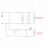
I've just traced out the crossover as photo'ed on the AliExpress link. It's somewhat odd! I would ignore the switch labels for a start. Just for fun I'll draw the schematic in XSIM, but I can only guess some of the component values. The sales pitch says it's for 4Ω or 8Ω drivers, but obviously the terminating impedances on each segment of the crossover are going to affect the crossover frequencies, so I don't know how that is supposed to work. And since the effective inductances of the drivers that will be connected to the crossover are also unknown, even XSIM isn't really going to be able to predict the crossover's behaviour properly.
Last edited:
Mine doesn't have the upper crossover frequency of 3500 khz writing on the backing panel as all the others I've see pictured do.
I've been looking at a lot of crossovers online and If there $50 or less each they don't usually list the crossover frequency, frustrating for me.
I've been looking at a lot of crossovers online and If there $50 or less each they don't usually list the crossover frequency, frustrating for me.
Can you read the values of the components (especially the inductors)? I can simulate the crossover for you if you want but I would need the values of each component. I think I can figure out how they are connected based on the picture of the backside of the board but a schematics would be great too...

It's a 3 way crossover
There are no switches
The size' of the biggest inductor should suggest a (insert exact valute) <1000 Hz cross
The second in size' of inductors is the 2nd pole of the HP filter in midrange path...
The capacitor before it, its value should suggest the (ballparkin...) HP crossover point
The two big resistore are on the midrange, they make a voltage divider, an L-pad.
There are no switches
The size' of the biggest inductor should suggest a
(insert exact valute) <1000 Hz crossThe second in size' of inductors is the 2nd pole
of the HP filter in midrange path...The capacitor before it, its value should suggest the (ballparkin...) HP crossover point
The two big resistore are on the midrange, they make a voltage divider, an L-pad.


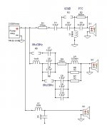
I've attempted to draw out the crossover. Please feel free to make corrections.
Notes:
Notes:
- The RLC numbering does not line up with the silk screening on the actual item.
- The switches are shown as open resistors; short circuiting the open resistors is equivalent to closing the switches.
- Where values could not be read off the actual components, the values are merely conjecture.
Attachments
I think any crossover is completely specific to the drivers and desired response.
Looking at the crude driver data you've posted, I'd be suggesting crossovers at ~200Hz and ~2kHz. Have you selected a tweeter? You'd ideally find one with an resonance of well below 1kHz, such as SB26STAC-C000-4, SB26STC-C000-4, or RST28F-4 if you wanted to stick with Dayton.
Looking at the crude driver data you've posted, I'd be suggesting crossovers at ~200Hz and ~2kHz. Have you selected a tweeter? You'd ideally find one with an resonance of well below 1kHz, such as SB26STAC-C000-4, SB26STC-C000-4, or RST28F-4 if you wanted to stick with Dayton.
Last edited:
I'm impressed you can do that, although I don't know how to internet the data. Do you know where the crossover points are?
The reason I'm asking is that one the previous posts has a link to pic that shows it has a lower crossover of 2600 khz and an upper of 3500 khz typed on the backing plate. Those crossover points are right on the top edge frequency before cone breakup on my 10" and 6.5" (as above in pics)
If the lower crossover point is 1000 khz I'd be much happier with that.
Here is pic re 2600
Tim
Weah 3509a 2600 khz 3500 khz crossover point s?
Last edited:
 Thread moved to Multi-Way
- Home
- Loudspeakers
- Multi-Way
- New Crossovers with Hz/db switches & DIY speakers