Shopping list collated!
For a pair of Amplifiers and a pair of PSU with a rectifier set each and one transformer comes to a grand total of £113.
£43.06 of this is for the Amplifier components including £10.98 for a very large heat sink that will serve both.
£70.51 is for the transformer and both PSU/rectifier circuits.
This time round I will get the parts for the amplifiers.
regards
Foo
Are you planning for PCB group buy?
By the way your 3D modelling is very good, which software are you using.
By the way your 3D modelling is very good, which software are you using.
Having used regulators to "hide" the transformer and rectifier, then your amplifier will neither care nor know what sort of power diodes you've used IF they are slow enough that they don't overcome the HF coverage of the regulators. Do again, please review the rectifier shown by Mark Houston right here: Synergy - LM3875 Gainclone Amplifier (Chip Amp)
Concept: You need to stay closely to normal at the beginning of the amplifier build. After running fairly standard, then, with a nice solid baseline to start from, after that, you can begin voicing/fine tuning one option at a time, to see what they do, see how they sound different, and see how they work together. Super fast rectifier in combination with not so fast regulators could foil, block, confuse, and overheat such efforts. Those regulators need a job they're able to do. Use ordinary rectifier. . . or add a fan or a scope to your list.
As for resistor expense, howabout a "variety pack" instead of hundred lots of single values?
You might want to double-check that LM3876TF pricing since it seems to be double or about as much as a manufacturer direct sample. Just double-check. Also "TF" is the conveniently safer pre-insulated version. Otherwise, if using the "T" version, you'd need to add shoulder washers and insulator pads to your list.
Last edited:
Hello there
Kuldeepsingh - I'm more likely to release all the artwork, parts list etc into the public domain for all to have a go at should 'they' find it of interest. As far as I can see there are far more interesting projects on this site.
The 3D images are done in Google Sketchup, free addition, at 1:1 scale.
Daniel - Does £76.38 sound better? Resistors in packs of 10 at less than 30p per pack. Also the LM3876T IC is available from RS £5.75 each. For these and the resistors I can get them 'over the counter' at my local RS so no delivery charge.
Diodes - 8A 50V Bridge rectifiers in a SIL package instead. Standard type 4 for £0.98p
I concur with you that I should start with a good working base set up before trying to go 'exotic' and possible having issues
Also Once I have successfully made these and run them I will probably revisit the PCB and 'open it up' to allow a wider range of component footprints to be used but maintaining the short signal lines and separation.
regards
Foo
Attachments
Oh no. Use the square.Diodes - 8A 50V Bridge rectifiers in a SIL package instead. Standard type 4 for £0.98p
Attachments
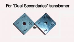
For LM3876T add the costs of insulator pad and shoulder washers. Silver tab is at V-!!!Also the LM3876T IC is available from RS £5.75 each.
Compare that LM3876TF (black tab) doesn't require those insulators added.
Hi Daniel
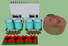
I have a plethora of 'Top hats' and thermal pads I have for other projects. Here is the revised rectifier, See attached image.
I am also starting to look at alternative layout and enclosure options. This project is more fluid than a very fluid thing!
regards
Foo
I have a plethora of 'Top hats' and thermal pads I have for other projects. Here is the revised rectifier, See attached image.
I am also starting to look at alternative layout and enclosure options. This project is more fluid than a very fluid thing!
regards
Foo
Attachments
Hi All
Just waiting on monies hitting my bank account, tomorrow hopefully, and then I can order the first group of parts.
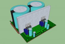
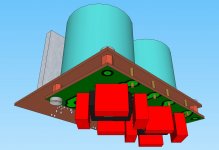
I've been playing around with an idea for a lay out and enclosure.
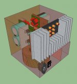
A cube 165.5mm on a side. The 100mm X 165.5mm X 35mm Heat sink recessed into the back, but open, to maintain the 'cubeness'.
To save space the rectifiers will be mounted back to back with their regulator partner circuit. I'm going to adjust the rectifier boards slightly so that the Power out to power in points, of the regulator, line up when the pairs are fitted together which will allow a very short piece of wire to link between them. Care will be taken with spacing and fixing to avoid short circuits.
The current image also shows the addition of a selector switch and extrra RCA sockets in the back. I aim to fit 3 inputs. This bit will follow once the initial modules are built, tested and no magic smoke escapes 😱
Other than the circuit build the above is still a WIP. The first 'enclosure' is likely to be a slab of MDF used to bolt everything down to for trials and testing.
As an aside I have had my DMM plugged into a mains socket all day. The Voltage has been stable a 246VAC. So the figure of 1.06 needs to be thrown into the math I guess.
regards
Foo
Just waiting on monies hitting my bank account, tomorrow hopefully, and then I can order the first group of parts.
I've been playing around with an idea for a lay out and enclosure.
A cube 165.5mm on a side. The 100mm X 165.5mm X 35mm Heat sink recessed into the back, but open, to maintain the 'cubeness'.
To save space the rectifiers will be mounted back to back with their regulator partner circuit. I'm going to adjust the rectifier boards slightly so that the Power out to power in points, of the regulator, line up when the pairs are fitted together which will allow a very short piece of wire to link between them. Care will be taken with spacing and fixing to avoid short circuits.
The current image also shows the addition of a selector switch and extrra RCA sockets in the back. I aim to fit 3 inputs. This bit will follow once the initial modules are built, tested and no magic smoke escapes 😱
Other than the circuit build the above is still a WIP. The first 'enclosure' is likely to be a slab of MDF used to bolt everything down to for trials and testing.
As an aside I have had my DMM plugged into a mains socket all day. The Voltage has been stable a 246VAC. So the figure of 1.06 needs to be thrown into the math I guess.
regards
Foo
Attachments
Hi All
A slight problem has arisen! The 10ohm 5W resistor - I've just noticed that the ones I was going to get are in fact wire wound. I have seen, on the forum, the use of wire wound resistors to be ******** as they will behave like an inductor coil.
As this is the resistor that is, in some cases but not all, the one that has an air formed coil slipped over it, as per the circuit I'm using I guess this could throw things adrift.
Ebay has loads but all in Hong Kong 😡
But there is a suppler in the UK -
Ye Shoppe Online
But! The nearest value is either 9R1 or 11R going lower in value is probably not a good idea so would the 11R be OK?
These are the only non wire wound resistors I have found so far.
regards
Foo
Hello Andrew HNY!
Could you expand on this please? The instructions that were with the original Schematic said to fit the one in the other. Or is this a way round having to use a wire wound resistor?
Following your guidance would I just solder the coil and the resistor, in parallel, but side by side rather than one within the other?
I am also adding a multi turn trim pot to each side of each regulator board to allow fine tuning of the voltage levels.
regards
Foo
The field inside the coil can affect the way the resistor passes signal.
The field around (outside) the coil can affect nearby circuits and be affected by nearby metal work.
For these reasons I locate the L//R off PCB in the cable route to the speaker terminals.
The field around (outside) the coil can affect nearby circuits and be affected by nearby metal work.
For these reasons I locate the L//R off PCB in the cable route to the speaker terminals.
Yes to wirewound if building a custom speaker to help level the response of your amplifier. Otherwise the answer is no wirewound.can I use a wire wound resistor without worry then?
regards
Foo
Resistor:
Use 9.1R non-inductive resistor for good results because quality treble results can be scarce with spike system chips. The expense is justifiable for the non-inductive resistor in the case where margin for error is worse than zero.
Inductor:
You can install the inductor on trackside to meet your spacing requirements. An inductor of that type is like a little pistol so keep small signal away from the circular "openings" of the inductor coil. If acceptable spacing cannot be done then move the inductor and resistor combo to the speaker jack.
Last edited:
Hello There
Thanks Gentlemen!
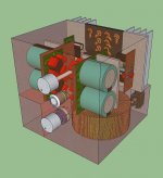
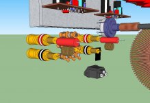
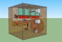
Here are a few mock ups with the trim pots added to the PSU and the L//R shown directly fitted to the Audio out post.
The 'possible' enclosure is now 200mm on a side. This small change has increased the available space for 'future' additions.
regards
Foo
Thanks Gentlemen!
Here are a few mock ups with the trim pots added to the PSU and the L//R shown directly fitted to the Audio out post.
The 'possible' enclosure is now 200mm on a side. This small change has increased the available space for 'future' additions.
regards
Foo
Attachments
Will it be possible to reach the trim posts, via the ventilation holes, with the chassis fully assembled?
A couple of plastic guide tubes/cones will avoid accidents.
A couple of plastic guide tubes/cones will avoid accidents.
Hi Andrew
The holes don't line up well enough, if at all, and I certainly see your point.
Construction wise I am thinking of the top being a removable panel to allow access. Perhaps take this further and set it up so the structure is made up as a pair of U shaped sections rotated 90 degrees to each other so they they interlock.
This would be simple and allow access all round as well for 'maintenance' and 'extras'.
The front, back and base will be aluminium. The sides and top a stained wood. Possibly.
One extra circuit I will add will be a time delay tied to the mute control of both channels to keep the speakers muted during the 'power up' cycle. My Late mothers JVC system had a 5 second delay, I had to replace one of the relays for her, so I will take that as a start point.
I can either use a 555 based circuit. Or go for a simpler transistor/capacitor based delay. I will have to see if a differing voltage will be needed of course.
regards
Foo
Last edited:
Hello all
Well my orders are ready and once the final drops of finance appear I'm ordering.
In fact.... Everything! Barring RCA sockets, speaker posts, power socket.
£119 in total. Three suppliers and Ebay. I have also added a 50K ALPS pot to the rapideonline order. One pair of caps and the 5W 9R1 metal film resistors from AmpPartsCollective and RS for the Amplifiers chips and small quantity resistors.
For the PSU regulator I have picked a 2K resistor to go with a 2K bourns trim pot to set the voltage output. I need 3.2K +/- tolerances to set the +/-35V.
A few additional components, poly caps, have been ordered having reviewed the PSU on Decibel Dungeon. These go on the outputs of the PSU modules.
A panel of copper clad is also on order to make the PCBS.
For the coil I have the 1mm enameled copper wire. Instructions are 13 turns on a 10mm Former, close wound. This is to make it a 0u7H. I presume I can change the physical size of it so long as it remains at the 0u7H?
I just fancy reducing it's diameter so it looks more 'elegant'. I have been playing with an online coil calculator which suggests it can be done but I have noticed that this effects the 'self resonance' and the 'stray capacitance' also changes. Are these particularly important?
Other additions for later will be a Speaker protection circuit. The vellaman circuit looks to be popular. The mute function needs a little thinking about. I want to use a double pole single throw type relay to handle this but I want a DC power off sub circuit to complement this so that the relays mute the amps as soon as power is switched off.
regards
Foo
Last edited:
- Status
- Not open for further replies.
- Home
- Amplifiers
- Chip Amps
- New amplifier...possibly..