Hello there
They look good. The 2nd and 3rd are small enough to fit in the case. But I am going to go the toroid route with this. I have noted down the SMPS details though for future reference.
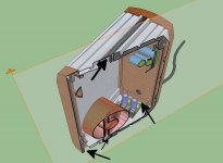
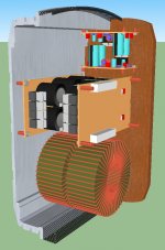
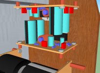
I have 'knocked up' a scale drawing of the unit with a pair of SMPS PSU's inside and another with a pair of toroids.
Now I have been looking at the ground lift/safety earth issue. Given that I will be running this unit as a dual single rail where do I take the Zero volt line to?
Obviously the earth line itself is to be hard wired to the casing halves. I am also assuming I need 2 circuits to cover each channel.
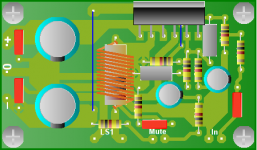
I have etched the 1562 PCB's today. Some of the finest traces I have had to do so far. One PCB will need visiting with strands of wire, and solder, to just bridge some faults on these fine traces 😡
regards
Fooboo
They look good. The 2nd and 3rd are small enough to fit in the case. But I am going to go the toroid route with this. I have noted down the SMPS details though for future reference.
I have 'knocked up' a scale drawing of the unit with a pair of SMPS PSU's inside and another with a pair of toroids.
Now I have been looking at the ground lift/safety earth issue. Given that I will be running this unit as a dual single rail where do I take the Zero volt line to?
Obviously the earth line itself is to be hard wired to the casing halves. I am also assuming I need 2 circuits to cover each channel.
I have etched the 1562 PCB's today. Some of the finest traces I have had to do so far. One PCB will need visiting with strands of wire, and solder, to just bridge some faults on these fine traces 😡
regards
Fooboo
Attachments
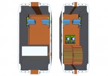
One enclosure? Where is the cool air intake? Where is the hot air output?
Capacitors don't last inside of ovens (5000 hours is insufficient).
Real bridge rectifier looks like:
~+
-~
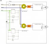
Reference output of the Ground Loop Breaker goes to the power supply board:
To the center tap of a split rail supply, also called zero volt.
Or, to the Negative of a single rail supply, since the car chip is a negative ground model, as is the typical car.
P.S.
There is high variety amongst car chips. Some of them are very impressive, most a are a mid-fi with a pleasant tone but not penultimate clarity, and some are terrible as if a flat raspy low resolution presentation. In this case, if I were you, I'd get one of those up and running and check it out with an SMPS (12.7v to 15v range) before spending it up with luxuries such as a fully dual mono build. Some of that isn't an effective place to spend. Also Toroids don't like to be stacked like that. Personally, I'd use ONE 15+15 dual secondaries transformer and a pair of regulators (one reg per each channel). See Decibel Dungeon about the regulators (or capmulti), which are an audio quality upgrade. You'd just be building two V+ portions to get your dual mono regulated power.
Capacitors don't last inside of ovens (5000 hours is insufficient).
Real bridge rectifier looks like:
~+
-~
Reference output of the Ground Loop Breaker goes to the power supply board:
To the center tap of a split rail supply, also called zero volt.
Or, to the Negative of a single rail supply, since the car chip is a negative ground model, as is the typical car.
P.S.
There is high variety amongst car chips. Some of them are very impressive, most a are a mid-fi with a pleasant tone but not penultimate clarity, and some are terrible as if a flat raspy low resolution presentation. In this case, if I were you, I'd get one of those up and running and check it out with an SMPS (12.7v to 15v range) before spending it up with luxuries such as a fully dual mono build. Some of that isn't an effective place to spend. Also Toroids don't like to be stacked like that. Personally, I'd use ONE 15+15 dual secondaries transformer and a pair of regulators (one reg per each channel). See Decibel Dungeon about the regulators (or capmulti), which are an audio quality upgrade. You'd just be building two V+ portions to get your dual mono regulated power.
I am also assuming I need 2 circuits to cover each channel.
Given that the rule for avoiding ground loops is "Once Met" then I think that you are correct to use one ground loop breaker per each channel since Dual Mono is supposed to be electrically identical to Monobloc, with the sole exception the number of enclosures used.
Its yet another expensive enhancement that I've never seen used with a car chip. Before you go much further, please check out the price of a MyRef. The difference in cost between that and a car chip is only a tiny fraction of the total cost.
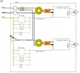
The two transformers give you two isolated amplifiers.
Yes, each amplifier needs it's own connection to Safety Earth.
Now you have dual mono inside a common chassis.
If you can, keep the two isolated amplifiers ALWAYS isolated from each other. The ONLY connection between them must be the two Disconnecting Networks.
Now to discuss the Disconnecting Networks.
1.) the 10r 5W resistor does not pass power. It only passes leakage current to chassis. A 1/4W resistor is sufficient here.
2.) the 100nF capacitor only passes leakage current to chassis.This can be a low voltage type. A small 50V ceramic is sufficient.
3.) one can add a switch across the DN. This switch will be in parallel to the other components in the DN. When the switch is open the DN operates as expected. When the switch is closed the DN is shorted out and you have a direct connection from chassis to the Main Audio Ground. This switch could be termed a "ground lift" switch.
NOTE this ground lift switch does not break the Safety Earth to PE, nor does it break the Safety Earth to Main Audio Ground. The switch is "safe" in both positions.
Last edited:
Now to discuss the Disconnecting Networks.
1.) the 10r 5W resistor does not pass power. It only passes leakage current to chassis. A 1/4W resistor is sufficient here.
Hi Andrew, I though Rod Elliot suggested the 5W because of leakage currents up to 5 Amps...?!
see here
Hi All
@Andrew. Thanks for the clarification. Much appreciated.
@Daniel. I know. They are only car amp chips. At this point, there is much cogitation ongoing, I may well save the ali shells for my LM3876TF/LM3886TF. (Rapid no longer stock the **76 nor does Cricklewood but they do have the **86). RS do stock the **76 though.
But the implementation will be much the same bar the single large toroid for the **76/**86. But what I learn here is as applicable whichever way I go.
Cost wise it's not that bad. More importantly for me I am having fun in the practical and picking up some of the theoretical.
Air Vents! Good call. I have changed the wood struts to metal mesh and opened up the base of the front and rear panels. This should allow circulation. I can always add a larger mesh covered opening in the back panel if required.
There is a chance that once complete this pair of amps may segue sideways and be pressed into service in a prop build.
regards
Fooboo
Attachments

Sir, the average quality of resistors has been dropping dramatically. We have no way of knowing if the 1/4W resistor is of the expected durability. The availability of 1/2w resistors is also affected by this variance. They might wear out, and then the Ground Loop Breaker may not work exactly as expected.. . . A 1/4W resistor is sufficient here. . .
This could cause an inconvenience in the same way that 60/40 solder can cause an inconvenience--looks like it should be working but there's poor or absent conductivity, or later on someday, there's poor or absent conductivity and no visible problem.
So, perhaps a 1w, 3w or 5w resistor? The quality is normally useful.
And, what sort of solder were we supposed to be using?
Thanks!
. . . Air Vents! Good call. I have changed the wood struts to metal mesh and opened up the base of the front and rear panels. This should allow circulation. I can always add a larger mesh covered opening in the back panel if required. . . .
I'd like it if you maintained the non-conductive front panel. I'm Not in favor of either a voltage or a reference for fingers.
P.S.
Your car chips are single rail. One dual secondaries transformer is what you need. But that should be used for regulated power, with two rectifiers (plus caps) and Two V+ Regulators. Considering the isolation at the transformer and a regulated supply individual for each channel, that is a dual mono power circuit--a very good dual mono power circuit for single rail amplifiers.
Split rail amplifiers would use dual transformers for dual mono, but are you building a split rail amplifier? No. Not with TDA1562Q.
Good spendy audio enhancements include Regulators and Low Impedance caps. Those two things really help car chips. They're awful on unregulated power no matter how high extraneous transformers could be stacked to do the job of an ordinary brick. 🙂
Sure, that's a financial aspect rather than purely electrical; but, whatever you do, please remember to use regulated (or capmulti) power with your car chips.
Last edited:
The ESP article talks of a "few milliamps" of earth leakage current.
That leakage passing a 10r resistor will give rise to a few tens of milliwatts of resistor dissipation (Daniel, you're away in dream land).
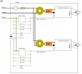
I see the diagram now includes the ground lift switches. As far as I know this is the only safe way to incorporate a ground lift switch. Some combinations of equipment will sound better with the switch closed, while other may better suit the switch open.
I don't mind a master fuse at the main entry into the amplifier, it does offer more safety the closer it is to the input location.
But I recommend that each transformer is fitted with it's own close rated fuse.
Although it's only a drawing, could you show the main Green/Yellow wire from the mains cable going short and direct to the chassis? The DN can still connect to chassis as shown at some remote location. The chassis will pass the Fault Current.
That leakage passing a 10r resistor will give rise to a few tens of milliwatts of resistor dissipation (Daniel, you're away in dream land).
I see the diagram now includes the ground lift switches. As far as I know this is the only safe way to incorporate a ground lift switch. Some combinations of equipment will sound better with the switch closed, while other may better suit the switch open.
I don't mind a master fuse at the main entry into the amplifier, it does offer more safety the closer it is to the input location.
But I recommend that each transformer is fitted with it's own close rated fuse.
Although it's only a drawing, could you show the main Green/Yellow wire from the mains cable going short and direct to the chassis? The DN can still connect to chassis as shown at some remote location. The chassis will pass the Fault Current.
Last edited:
Daniel.
Work as expected?
What do you expect of the DN?
It must survive long enough while passing fault current to PE until after the fuse ruptures and the arc extinguishes. It has no other purpose.
The resistor and capacitor have been added at this convenient location to introduce a low impedance route for HF artifacts. This might not be the optimum location to provide that low impedance path.
Now, when or if 30mAac of leakage current passes through the DN. The voltage across the resistor will be ~430mVpk. The diodes might just be starting to pass a few uApk.
If the leakage were to increase to 150mAac then the diodes will pass most of this, because they will limit the voltage drop to ~ 600mVpk and thus the 10r resistor will pass ~ 60mApk at the extreme voltage of the AC waveform. The other 90mApk will pass through the diode/s.
When the AC leakage current drops down to ~60mAac then the diodes pass a very low proportion of the leakage current and the resistor ends up having to pass the majority of this. The maximum dissipation is ~ 0.5V * 0.5V / 10r ~ 0.025Watts. Just 10% of the dissipation capability of a 1/4W resistor.
The ESP article talks of a "few milliamps" of earth leakage current.
That leakage passing a 10r resistor will give rise to a few tens of milliwatts of resistor dissipation (Daniel, you're away in dream land).(...)
in Rod's article...
"It is not uncommon to have a voltage of 1V RMS between the earth connections of power outlets that are wired separately back to the switchboard. This small voltage, with a total resistance of perhaps 0.2-0.5 Ohm, will cause a loop current of 2 to 5 Amps, all of which flows in the shield of the interconnect. This is sufficient to cause a voltage difference across the interconnect, which the amplifier cannot differentiate from the wanted signal. By breaking the loop with the 10 Ohm resistor, the current is now less than 200mA, and the voltage across the interconnect will be very much smaller, reducing the hum to the point where it should no longer be audible."
so it's not only for when a failure occurs, but also to reduce "floating" loops which one could have (or not) ... the way I see it Rod's talking about reducing interference from the mains side to the amp.... but your math do make sense 😕
Correct.Daniel, you're away in dream land
I would like to say that the 5w and 10w resistor selections is a justified expense, but cannot do so, considering that the voltage is limited to 0.75v by the heavy duty diode shunt, and the current is limited by the 10 ohm value of the resistor itself.
This was so obvious that I didn't see it--like searching for the keys all over the house because they are in the doorknob. 🙂
Solder joints with 60/40 do fail though.
In the Ground Loop Breaker, it is possible for a power surge condition to occur where there is too much voltage for the 35a bridge to use, while simultaneously insufficient current to trip the mains breaker.
It is important to reduce this variety by installing mains fuses at the amplifier.
If you don't want a fault condition to simultaneously catch your diode bridge sleeping because of power surge over-voltage, then, either protect the bridge from over-voltage or make your resistor strong enough to blow your amplifier's fuses unassisted by the (fainted) bridge.
Result (a production priced approach):
8a or smaller mains fuses, preferably smaller
MOV to clamp 700v or smaller figure
KBPC1010 (700v RMS) or better bridge
1/4w resistor or better
100nF cap
See how the MOV (or other surge protection) relates to the voltage capacity of the bridge? See how the Fuses relate to the amperage capacity of the bridge? Within this scenario, the 1/4w resistor works.
or
Amp has mains fuses, and. . . Ground Loop Breaker has heavy duty bridge, a 100nF cap and a resistor (at least 10w) strong enough to blow fuses by itself rather than any assumption the bridge could work during a high voltage surge or ESD. Basically, if omitting the MOV protection, use a really very strong resistor in your Ground Loop Breaker.
Last edited:
Evening all
Right then. The TDA1652 circuits will be built but are going to be pressed into service elsewhere. Elsewhere being the power amp for a voice modulator circuit I've built. This being a new variant which has only the sound to light circuit and modulation circuits on it. It is designed to be used with an external amplifier of the 'users' choice. Definition of 'users' being 'Full size Dalek prop owners'. 😱
A alternative version has a built in TDA2003 bridged amp as does the predecessor to these versions. An amp which works very well indeed.
SO! on to my plans for an LM3876T build. This will be what is fitted into the ali case. I have been reading so much information here, NUUK's, and Mike F's site my brain is screaming for mercy
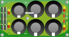
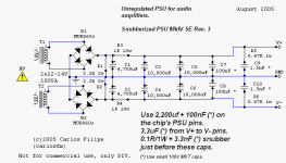
Using the information I have drawn up, based on existing works, the PCB for the LM3876 and the regulator board based on CarlosFm's snubberized circuit. Other than adding, on the amp PCB extra pads to allow for different pitch capacitors and making a lot of the pads, in the heavy traced areas, thermal types, everything is as is.
I have used data sheets to accurately draw the components so the spacing should all work out. On the regulator PCB R3/4 will be mounted on the underside as are a pair of 100n caps on the last pair of electrolytics.
The resistors, the higher wattage ones, are all on my watch list on ebay as are a pair of LM3876 chips and MUR diodes. Everything else I can get from rapidonline.
I have tidied the ground lift/safety earth diagram up as recommended by Andrew as well.
regards
Fooboo
Right then. The TDA1652 circuits will be built but are going to be pressed into service elsewhere. Elsewhere being the power amp for a voice modulator circuit I've built. This being a new variant which has only the sound to light circuit and modulation circuits on it. It is designed to be used with an external amplifier of the 'users' choice. Definition of 'users' being 'Full size Dalek prop owners'. 😱
A alternative version has a built in TDA2003 bridged amp as does the predecessor to these versions. An amp which works very well indeed.
SO! on to my plans for an LM3876T build. This will be what is fitted into the ali case. I have been reading so much information here, NUUK's, and Mike F's site my brain is screaming for mercy
Using the information I have drawn up, based on existing works, the PCB for the LM3876 and the regulator board based on CarlosFm's snubberized circuit. Other than adding, on the amp PCB extra pads to allow for different pitch capacitors and making a lot of the pads, in the heavy traced areas, thermal types, everything is as is.
I have used data sheets to accurately draw the components so the spacing should all work out. On the regulator PCB R3/4 will be mounted on the underside as are a pair of 100n caps on the last pair of electrolytics.
The resistors, the higher wattage ones, are all on my watch list on ebay as are a pair of LM3876 chips and MUR diodes. Everything else I can get from rapidonline.
I have tidied the ground lift/safety earth diagram up as recommended by Andrew as well.
regards
Fooboo
Attachments
Last edited:
LM3876 now? Okay, that'll be a good workout. Clearer, less stable, prone to misbehave, far more difficult to regulate frequency response and tone, but yet they are clearer.
Huge mistake to spend as much for this as a MyRef (howland current pump), but it is doable.
It is a big fight and alright if you win.
Power supply board,
missing resistors make some of the caps in the wrong place:
Since the R is omitted from your CRC power supply, re-locate one pair of the 10kuF from the power supply board to the amplifier board. The slight resistance of the interconnect cable has now formed the missing "R" Use a fairly light gauge cable for V+ and V- (but make a safe choice), and have your 0v cable at double thickness. 🙂 This is probably appropriate, since spike system chips are more likely to have useful output when there are large caps at point blank range. Otherwise, it may be abrasive except for dull or custom tuned speakers.
Designs that dodge the spike system noise:
1). Audiosector and 47 Labs use power circuit (specific big caps at point blank range to chip) to swamp spike noise.
2). Parallel amplifiers fight off sporadic noise by brute force, including spike noise.
3). Nested, composite and Howland current pump override the spike noise sound of the amplifier by enclosing it in the feedback loop of a small signal opamp.
These three things above, avoid an abrasive tone from spike chips like LM3875, LM3876, LM3886, LM4780 and others that are equipped with a noisy current limiter sealed inside the chip. I'd suggest to review the working designs that circumvent the noise.
Non specific power board snubbers:
The snubbers shown on the output of the power board also happen to be the approximate performance for a polyester dip (blob) cap, which are very inexpensive, and so I would suggest that instead of simulating the correct part with a pile-up of expensive parts, why not simply buy the right part, since it costs a great deal less?
Without laboratory measuring tools, you need to be very very gentle with power snubbers so that there are no abrupt disturbances that could cause ringing. Just avoid non-specific use of high efficiency parts in filters, because it is possible to have a big bill for decreased performance.
Output zobel datasheet difficulty:
This also applies to the cap on the speaker output snubber/zobel, since 2.7R is otherwise a nonsense value and by this, National Semiconductor has suggested to use a polyester dip cap, adding its own internal loss from inside the cheap cap to the 2.7R spendy resistor to arrive at the correct combine resistance value. Production lines wouldn't use an expensive box cap for speaker zobel, and so the datasheet supports the expected choice of cap for mass production, at the time of publication. For an unexpectedly high efficiency cap, like a box cap or a ceramic, compensate the value of the resistor, larger, so that the RC can work and you may need a smaller value cap in some cases.
If it comes to a hard choice, try this: Instead of omitting the zobel because of bad sound, have your schematic show 6.8R with 10nF so that nobody will ever be tempted to omit. Its far off the audio band, but still able to reduce RF while not putting any extra load on the amp. More specific values could work better, but any working zobel is better than omission.
P.S.
Your TDA1562q as well as LM1875, TDA7294, STK and Discrete, all offer more flexible design because they don't contain a noisy inbuilt current limiter. As for a level response, these don't put up a fight at all. Of those, the TDA7294 does have a current limiter that doesn't screech, but rather offers a slight challenge at producing the lowest notes of the audio band since those do require the most current.
P.P.S.
Can I have a Dalek with a 50 watt switching power amp aboard? I don't know what its for, but I want it! 🙂
Maybe we could make the Dalek dance around and jam out like a gogo dancer? This would seriously frighten the postman. lolz!!!!! 😀
Last edited:
Hi there
Just doodling a bit and perusing the forum a lot.
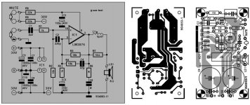
I have attached the schematic I'm using for both the amplifier and the carlosFM type snubbed power supply/regulator.
I am looking at a 25V dual secondary supply which will produce around 35.25V
One query I have. What is the minimum Ampere on the secondary coils I should not go below. Depending on the answer I may have to alter my set up a bit to suit a different pair or single transformer to ensure I meet or exceed this .
The 'missing' resistor is on the back of the regulator PCB, if this is the one you mean. I'm up for a challenge. I regularly build a TDA2003 bridged amp as part of the current voice mod I build so fingers crossed this will stand me in good stead.
See also the image of my friend Dalek Storm. He dances for no one 😀
regards
Fooboo
Just doodling a bit and perusing the forum a lot.
I have attached the schematic I'm using for both the amplifier and the carlosFM type snubbed power supply/regulator.
I am looking at a 25V dual secondary supply which will produce around 35.25V
One query I have. What is the minimum Ampere on the secondary coils I should not go below. Depending on the answer I may have to alter my set up a bit to suit a different pair or single transformer to ensure I meet or exceed this .
The 'missing' resistor is on the back of the regulator PCB, if this is the one you mean. I'm up for a challenge. I regularly build a TDA2003 bridged amp as part of the current voice mod I build so fingers crossed this will stand me in good stead.
See also the image of my friend Dalek Storm. He dances for no one 😀
regards
Fooboo
Attachments

Last edited:
Can you get C9 and C10 much, much closer to the chip? Really very close assists the tone of the Spike system chips. You will probably want 1500uF Panasonic FC or Nichicon FW/PW or a similar high performance model.
I have begun to add two things to my amplifier layouts:
*An additional 0v power tap private to the speaker return and zobel so that the speaker could have its own private line to the 0v tap of the power supply board.
*A "ground lift" resistor for small signal so that a resistor could be installed to lift signal star.
The funny thing is that one doesn't actually have to use those features, but rather they just force the layout to a star ground.
Although TDA7294 on a special circuit, with a light load and running rock steady on minimum voltage could be heatsinked directly to wood, its probably not a good idea for LM3876, since those run hotter and the LM3876 spike system would pipe up with loud screech. So, I think that you might want to revise the heatsink arrangement to use metal to heatsink LM3876TF.
Hi Andrew
Thanks for the heads up. I did some digging yesterday in an effort to discover the origins of the schematic and PCB pattern. It is from an Elector magazine from 1995. I also found it referenced on this site where the poster was having issues. They may have been due to builder error but the thread ended without any conclusion.
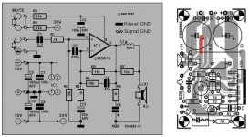
OK then. I have edited the schematic to remove the wire that ran between C3 and C6. Also moved the Power ground icon over to C3 and altered the original Power ground to represent Signal ground. I have added a 'Key' to the diagram for future reference.
I have also indicated, on the PCB top view, where the 'real world track' needs to be split to separate C3 and C6. I presume I need to add a new solder pad to allow the fitting of a Signal ground wire that goes to............a star ground on the chassis? connected to it's fellow amplifier?
Should the Signal GND IN, in the image, also be changed to keep things consistent and does this also have a bearing on the 'real world' set up of the amp? I will go and reread up on star GND and see if I grasp it's meaning and implication.
Just caught your post Daniel. Please ignore the diagram showing the chips on wood. A proper heat sink will be used. I'm just trying to arrange the modules for best fit and balanced wiring.
regards
Fooboo
Thanks for the heads up. I did some digging yesterday in an effort to discover the origins of the schematic and PCB pattern. It is from an Elector magazine from 1995. I also found it referenced on this site where the poster was having issues. They may have been due to builder error but the thread ended without any conclusion.
OK then. I have edited the schematic to remove the wire that ran between C3 and C6. Also moved the Power ground icon over to C3 and altered the original Power ground to represent Signal ground. I have added a 'Key' to the diagram for future reference.
I have also indicated, on the PCB top view, where the 'real world track' needs to be split to separate C3 and C6. I presume I need to add a new solder pad to allow the fitting of a Signal ground wire that goes to............a star ground on the chassis? connected to it's fellow amplifier?
Should the Signal GND IN, in the image, also be changed to keep things consistent and does this also have a bearing on the 'real world' set up of the amp? I will go and reread up on star GND and see if I grasp it's meaning and implication.
Just caught your post Daniel. Please ignore the diagram showing the chips on wood. A proper heat sink will be used. I'm just trying to arrange the modules for best fit and balanced wiring.
regards
Fooboo
Attachments
Last edited:
- Status
- Not open for further replies.
- Home
- Amplifiers
- Chip Amps
- New amplifier...possibly..