Hi Daniel
Yes indeed. All the caps are 105C, Panasonic branded.
Transformers - A pair of 160VA/230V with 2 X 25V Sec would probably be fine. But a pair of 225VA/230V with 2 X 30V Sec would give even better headroom I guess.
Based on information gleaned from Decibel Dungeon the 25V option after rectification would allow a minimum 30V regulation. I will be looking at using 8ohm speakers and following NUUK's guide from his website -
LM3875/6 -- 8 ohms -- 20-25 Sec VAC -- 28-35 volts DC after Bridge which looks like a lot of lee way.
regards
Fooboo
Foo,
are you confirming that you intend to use a regulated supply for the amplifier driving 8ohms speakers?
Then why stop at +-35Vdc?
are you confirming that you intend to use a regulated supply for the amplifier driving 8ohms speakers?
Then why stop at +-35Vdc?
Hello Andrew.
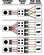
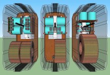
Yes. I am going to use a regulated PSU. One per amplifier. This decision was driven by the compactness of the regulated modules which will fit inside my case, without issue, unlike the unregulated version. A secondary bonus to this is the free space left in the enclosure which may be useful for a input selector and or conditioner circuit (in the future perhaps)
As for the voltage. I'm following guides at this point but I am aware that the LM3876 has a much larger voltage capability.
So I have checked out the options on rapideonline. A 160VA - 2 X 55V@1.45A per secondary is the next Voltage up in the current price range.
I can get 2 of the above for £43
Or I go for a single transformer feeding the pair of PSU modules an example being -
500VA - 2 X 50V@5A per secondary for £39.67
My thoughts on the single are cost/efficiency. With it's higher Amperage on the output it shouldn't struggle driving both PSU/Amplifiers either. Please correct me if I'm talking rubbish 😀
That said there is a 55V in the same price bracket. Other than upping the capacitor specs to suit. 100V for worst case I think.
Both the above, with the secondary coils in parallel there will be 9 - 10A available.
Any guidance on this aspect will of course be gratefully received.
Would the single transformer effect how the safety earth is done or is the dual system still applicable?
regards
Foo
The Safety Earth is the connection from the PE (third wire in the mains cable) to chassis.
It has nothing to do with transformer.
All exposed conductive parts must be connected to Safety Earth..
That requires things like terminals with an exposed metal part or a metal adjusting knob to be earthed to the chassis.
I don't understand your reference to 20Vac to 25Vac jumping up to 50Vac or 55Vac???
Then why stop at +-35Vdc?
Did I miss understand you?
Initially I was looking at 25V secondary coils which could peak at 38V after regulation and with supply voltage variables taken into account. The 35V was just to ensure I was within any variation of the actual figures for stability.
The leap after that was down to, well if I can why not, upping the anti as it were.
A transformer of 50 or 55V on the secondary coils would give me even more 'oomph' wouldn't it? I'm not looking to blow the windows out but in terms of how well the unit would perform with reference to clarity, etc etc.
I said something about having the secondary coils in parallel in the previous post as well, with reference to the single transformer. Please ignore that I don't know what I was thinking

Transformer per channel-
So either a pair of 160VA transformers with 30V (46V after regulation plus variables) on the secondary coils
Or a pair of 160VA transformers with 55V (84V after regulation plus variables) on the secondary coils.
Transformer for both channels-
Or a single 225VA transformer with 30V (45V after regulation plus variables) on the secondary coils.
Or a single 225VA transformer with 55V (83V after regulation plus variables) on the secondary coils.
The single transformer works out only a couple of pounds cheaper. But I think will not provide as much amperage as a pair?
If I have descended into pointless waffle please do feel free to point me in the correct direction.......... With a large stick if required 😀
regards
Foo
Last edited:
So how much voltage drop do you plan for the regulators? There is the big question. It needs compared to the current handling of the regulators, the current demand of the amplifier, the voltage output of the transformer and the voltage tolerances of the amplifier.
Given the information provided, I would guess on the 1 pair of 160va 30+30vac regulated down to a more suitable voltage according to the pertinent datasheets. One of the references says minimum 3v drop. I think that may be a minimum for heat at the regulator, minimum for effectiveness and maximum for current handling of the regulator chip, but I don't really know, so check these out:
Building a Gainclone chip amp with a regulated power supply (PSU).
Pedja Rogic Audio Pages - Chip Based Power Amp i.e. Gainclone - Regulated Supplies
The "effect on sound" audio feature you're actually looking for is the capacitive multiplier effect, such as:
Capacitance Multiplier Power Supply Filter
http://www.diyaudio.com/forums/solid-state/158843-capacitive-multiplier.html
Capacitance multiplier - Wikipedia, the free encyclopedia
Hi Daniel
That is the circuit I am working to 😀
As for the voltage drop - As little as possible. Rather than strangle the available voltage down to a 'given level' I want to use as much as is available whilst having a nice stable output.
So with the following-
25V output > 38V output after rectification. Regulate this to 25V
30V output > 45V output after rectification. Regulate this to 42V
35V output > 53V output after rectification. Regulate this to 50V
All the above have the 3V minimum which should create the minimum of waste. There may be other variables that effect the unregulated output voltage requiring a change in the amount the voltage is dropped but I hope it is clear how little voltage I want to waste as heat. I appreciate I need to look at the highest possible AC input and the lowest from the mains as this will effect the regulators load.
Something I need to clarify - On the datasheet for the LM3876. Where the power is quoted as -
Supply Voltage |V+|+|V−| (Input Signal) 84V.
Is this the voltage on both sides orrrrrrrrr is it the total between V+ & V-. ie. +42V + -42V.
Also one area that is not covered on the schematic or the minimal text for the design - R6 and C6 These are not given a value but having looked around it seems C6 is 100nF and R6 can be 2R7@1W. I can only find 2R2 with my 'usual supplier'. Would this do?
PCB wise I have made the diode rectifier portion a separate PCB. Variations on number of transformers, and regulator circuits are also being mulled over.
regards
Foo
Attachments


Last edited:
the two bars | & | mean Mod.
Take the +ve result of a +ve value and/or take the -ve value and invert it to a +ve value.
So Mod Vcc + Mod Vee = Rail to Rail voltage.
Note that 84 is an absolute maximum if signal is connected there is also a 94V max for no signal condition. These maxima must not be exceeded in worst case conditions.
I don't know why National show 2r2 for the output Zobel.
I have found that 10r works and 5r works. 5r (1W2) = 10r//10r, 10r (2W4) = 10r//10r + 10r//10r
If you want to try 2r5 since that is a lot closer to 2r2 then use 4 pieces of 10r 600mW resistor for the high power low value resistor.
Last edited:
Hi Andrew
Thank you for the clarification.
So a transformer with 25V secondary coils rectified and regulated to 35V, or there abouts is in order. Giving 70V peak to peak. Subject to variables of course
The zobel resistor is duly noted cheers.
I have a couple of voice mod orders coming in so I will soon have funds to do these and get going on this project
regards
Foo
transformer with 25V secondary coils rectified and regulated to 35V, or there abouts is in order
No.
if you want a +-35Vdc regulated supply, I would calculate whether a 30-0-30Vac or 35-0-35Vac transformer can do the job in all operating conditions.
I think your regulators may drop out if you use a 25-0-25Vac transformer.
At lower voltages I recommend the xVac = xVdc when you want a regulated supply. eg. for a regulated 15Vdc, use a 15Vac transformer.
.........Just when you think you understand....... 😱
Here's my next 'dumb' question. How are 'all operating conditions' discovered?
At this point please note I am numerically challenged to say the least so please keep it simple so I can understand.
Would part of the issue be that the previous calculations are also based on a 'no load' situation?
regards
Foo
Maximum and minimum Mains supply voltages.
Maximum and minimum transformer output voltages.
Maximum and minimum Ambient temperatures, Ta.
Maximum and minimum current draw. This could include one or more channels with blown rail fuses reducing quiescent current draw and thus increasing PSU Vout.
Maximum and minimum transformer output voltages.
Maximum and minimum Ambient temperatures, Ta.
Maximum and minimum current draw. This could include one or more channels with blown rail fuses reducing quiescent current draw and thus increasing PSU Vout.
Here are some figures based on a 160VA 230VAC 0-30 0-30VAC
Mains-230VAC> +/- 10% 207VAC min 253VAC max
Sec Coils 30VAC> 38.2VAC min 47VAC max
Plus 8% No load> 41.2VAC min 50.76VAC max
Temperature UK> 16C min - 35C max?
160VA Transformer/No load> 1.94A max 1.58 min
If I have these correct how are the figures applied?
regards
Foo
Mains-230VAC> +/- 10% 207VAC min 253VAC max
Sec Coils 30VAC> 38.2VAC min 47VAC max
Plus 8% No load> 41.2VAC min 50.76VAC max
Temperature UK> 16C min - 35C max?
160VA Transformer/No load> 1.94A max 1.58 min
If I have these correct how are the figures applied?
regards
Foo
One single 160va 30+30vac is big enough if you are using regulators.
Expected amount of power in watts times 1.5:
((55+55)*1.5) = 165va.
To further figure out your transformer, attempt to calculate how much voltage it can output while also trying to push one pair of 55 watt amplifiers sending AC music signal to 8 ohm speakers (6DCR). Subtract 3 and set your regulators to the result, or lower figure. The other way to say that is 3v less than rail sag condition.
You'll need four regulator chips to get their thermal interface large enough--or in other words, each amp has its own regulator board.
At this point, we have already prepared for thermal management of the regulator chips, and hopefully there is enough significant capacitance and filtering at the rectifier, to protect the regulators from noise based overheat. Right? Did you choose your PSU components based on cool running or something else? Please review.
Now to go check the amplifier datasheet. They're talking up a storm about 35vdc rails (and likewise not exceeding 70vdc span across both rails), therefore if you want the datasheet performance figures to be applicable, set the regs right on 35vdc.
Spike system data:
More than 35v rails to overrun (use 8 ohm speakers in this case)
Less than 29v rails to underrun
When operated outside of this range, the spike system is more likely to cause distortion more often.
The remaining question is thermal management of the regulators. When doing more work, they run hotter. Of course feeding them on clean and well filtered DC is mighty helpful as is using cap snubbed power diodes for cool running, not the HF noise blast of MUR for overheat. Of course having the amplifier run as stable as possible is also mighty helpful. These conditional aspects greatly affect thermal management and load capacity for real work = whatever isn't wasted into the heatsink.
Conveniently, the choice of a regulated supply means that the amplifier cannot "see" past the regulators and will not react with whatever reasonable choice is powering up the regulators. Therefore, sensible transformer and diode choices can be more easily applied for whatever is most helpful to regulators running efficiently.
Last edited:
Hi Daniel
The regulator is based on the one as described on the Decibel Dungeon site. See attached image. So the parts were chosen against this rather than my knowledge, or lack of it.
I have edited the image to add a pair of caps directly across the secondary coils and added caps across each diode of the rectifier sets. I have seen both these referenced on here and you mentioned the latter as well.
I did google for information on transformer selection. I think I ended up at the ESP site where there is a pretty comprehensive guide to PSU design. I'm afraid when it got to the math involved I blacked out........... (One day I'll pay a certain math teacher a visit and remonstrate upon his person in no uncertain terms how badly he screwed me up with the subject)
regards
Foo
Attachments
ARGHHHHHHH!
Ho Hum.
Whilst compiling my shopping list for this project I came across some minor 'issues'.
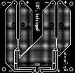
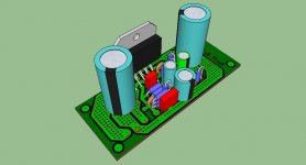
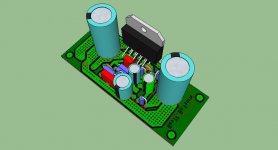
I have mixed up C2/C4 as far as physical outline goes. I can correct this with minimal disruption to the existing PCB pattern.
But, there had to be one somewhere, C1, the 2u2 cap, has a package footprint of 7.2mm X 7.2mm. This means a pretty large movement of C10, to the right is needed which buggers up the mounting hole in that quadrant. I really don't want to make the PCB bigger to accommodate this change. Also having tried out this change I just don't like the look of it......OK it's only a PCB pattern but I have my foibles 😀
So, C1, can I change to an alternate value such that I can use an item which has a footprint that falls within?
A resin dipped cap of 1uF perhaps? I could even fit 2 of these in parallel by fitting one topside and the other track side.
Or 220nF, seen on a few other designs that has a footprint of 2.5mm X 7.2mm.
Happy New Year All!
regards
Foo
Ho Hum.
Whilst compiling my shopping list for this project I came across some minor 'issues'.
I have mixed up C2/C4 as far as physical outline goes. I can correct this with minimal disruption to the existing PCB pattern.
But, there had to be one somewhere, C1, the 2u2 cap, has a package footprint of 7.2mm X 7.2mm. This means a pretty large movement of C10, to the right is needed which buggers up the mounting hole in that quadrant. I really don't want to make the PCB bigger to accommodate this change. Also having tried out this change I just don't like the look of it......OK it's only a PCB pattern but I have my foibles 😀
So, C1, can I change to an alternate value such that I can use an item which has a footprint that falls within?
A resin dipped cap of 1uF perhaps? I could even fit 2 of these in parallel by fitting one topside and the other track side.
Or 220nF, seen on a few other designs that has a footprint of 2.5mm X 7.2mm.
Happy New Year All!
regards
Foo
C1 (amp input cap):
Elna Cerafine 4.7uF or 3.3uF or 2.2uF // ~10nF polyester (that combination is named "classic combo")
Nichicon ES 2.2uF // 10nF polyester (turn the 2.2uF for clearest operation, add the treble with polyester)
Nichicon ES 1uF// Nichicon ES 0.5uF (set one "BP" mark inverse of the other)
Blackgate (see audiosector support forum)
Input transformer (see audiosector support forum)
These options are likely to outperform the overlarge selection on clarity.
Any of these prospects is for far higher quality audio than masking at the input with huge plastic and or motor caps for tone purposes.
For modification of input capacitor tone without endless capacitor selection, just make a clear choice and then add my "impedancething" circuit series to the input. It does not replace the input cap but rather adds the slight impedance screwup that audiophile caps can do for a more laid back sound. With clear input cap + impedancething, capacitor effect is entirely under your control via variable dial. The article on it is located in the triple lm1875 thread along with an economy audiophile sound card and a few other ways to do stuff on purpose rather than leave them to chance.
Last edited:
You might want to allow more spacing, including selectable pin spacing arrangement, for NFB cap. It seems crowded up against the feedback-shunt resistor and input jack. Sure, you could use 16v caps here, even recycled from computer motherboards; but, what you'll really end up using is whatever is clear, regardless of its physical size. It may as well fit gracefully. At some point, there may even be a trackside party, so be sure to leave room. The importance of this part is equal to, if not greater than, input cap. An NFB cap provides better speaker safety, a longer lasting amplifier and better dynamics; however, there will be a small selection effort, like interviewing a few candidates. Whatever works is more important that whatever fits. You might want to plan for that.
Hello Daniel
I've googled your recommendations, purely for visual reference, The uF ones are in fact electrolytics yes?
I know electrolytics can be used I'm just checking I am on the same track as yourself.
I quite agree that what works is more important than what fits. Fingers crossed your post gets me round the fitting issue without detriment to the end results.
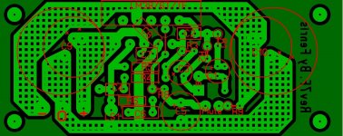
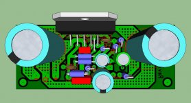
Something I picked up in another thread, as regards the PCB pattern, I have moved the edge of the trace, that runs under the LM3876T, so there is a gap between the board edge and the trace in question to avoid possible shorting issues with the heat sink.
Where I can I have added extra pads to allow 2.5mm - 5mm pitch caps to be swapped out.
Happy New Year All!
regards
Foo
I've googled your recommendations, purely for visual reference, The uF ones are in fact electrolytics yes?
I know electrolytics can be used I'm just checking I am on the same track as yourself.
I quite agree that what works is more important than what fits. Fingers crossed your post gets me round the fitting issue without detriment to the end results.
Something I picked up in another thread, as regards the PCB pattern, I have moved the edge of the trace, that runs under the LM3876T, so there is a gap between the board edge and the trace in question to avoid possible shorting issues with the heat sink.
Where I can I have added extra pads to allow 2.5mm - 5mm pitch caps to be swapped out.
Happy New Year All!
regards
Foo
Attachments
- Status
- Not open for further replies.
- Home
- Amplifiers
- Chip Amps
- New amplifier...possibly..