My post is Chinese Net,
but I cannot post here ,because upload failure.
Let me post it for you as below🙂 :
===================================
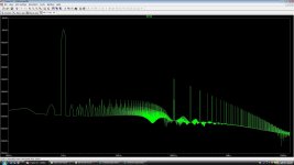
When a PreAmp circuit was simulated I found 1.5Khz appeared in FFT figure ,iuput were 1KHz.
That would be IM distortion frequency ?
But FFT should be just harmonics ,it isn't right?
It's puzzles me.
white PreAmp.jpg (172.37 KB)
下载次数:6
2010-6-19 13:33
Attachments
Last edited:
Let me post it for you as below🙂 :
===================================
When a PreAmp circuit was simulated I found 1.5Khz appeared in FFT figure ,iuput were 1KHz.
That would be IM distortion frequency ?
But FFT should be just harmonics ,it isn't right?
It's puzzles me.
white PreAmp.jpg (172.37 KB)
下载次数:6
2010-6-19 13:33
thank you
It should be understood that the JC-2 design is a PROVEN design topology that has been made in various versions for over 36 years. Slight deviations such as input fet types, output transistors or load resistors changes the distortion slightly, but not significantly. It is better just to build with the essential concepts intact. These are: Comp fet input, low value of load resistor, and fairly high current in the output transistors, 10ma min, 40-60 ma optimum. This will get you there.
It should be understood that the JC-2 design is a PROVEN design topology that has been made in various versions for over 36 years. Slight deviations such as input fet types, output transistors or load resistors changes the distortion slightly, but not significantly. It is better just to build with the essential concepts intact. These are: Comp fet input, low value of load resistor, and fairly high current in the output transistors, 10ma min, 40-60 ma optimum. This will get you there.
That's true,
to build with the essential concepts intact is important.
thank you .
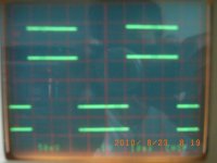
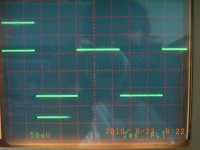
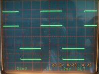
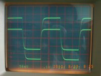
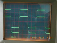
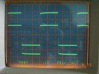
Measured some square wave forms in the following order for a new developing pre-amp base on JC-2 topology. Comments are welcome.
20Hz
100Hz
1KHz
10KHz
50KHz
100KHz
20Hz
100Hz
1KHz
10KHz
50KHz
100KHz
Attachments
Hi HKC !
Nice waveforms.
Is it from phono preamp or line preamp ?
Can you post schematic ?
eD
Hi eD
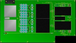
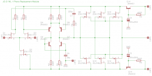
Sorry for late reply. It is a line pre-amp with 317/337 regulator, servo controlled. The circuit is not finalize yet. Here below is the pre-amp lay out:
Attachments
317/337 direct connected to preamp not best way.
Hi John
Thank you for the comment. What is the best way you would suggest?
By the way, would anyone can tell the sonic differences between LM & LT317/337?
Not the problem. 317/337 only good for hum filtering. Cap multiplier on EVERY gain block (4) necessary to buffer 317/337 for noise and transient problems.
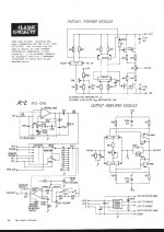
Anyone knows where we can get schematic of JC2?
marklev.com site is no more
and when I search with google there is not one jc2 schematic in the whole world
anyone have the original schema and can post it here as attachment?
we need it desperately!
/thanks
marklev.com site is no more
and when I search with google there is not one jc2 schematic in the whole world
anyone have the original schema and can post it here as attachment?
we need it desperately!
/thanks
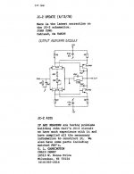
Thanks, Franz Gysi.
That one is good. Because it is an Updated version by John Curl himself.
Nice.
-----
Of course, I want the original JC2 paper, too.
As I remember it had power supply in same page.
That one is good. Because it is an Updated version by John Curl himself.
Nice.
-----
Of course, I want the original JC2 paper, too.
As I remember it had power supply in same page.
Attachments
OK, real problem. You must make 4 pairs of complementary capacitor multipliers for improved JC-2. This improves imaging and listening response. Each multiplier is composed of 1ea 0.5A transistor, 1ea 499 ohm resistor, and 1ea 220uf aluminum electrolytic cap 25V. Complementary transistor used on (-) supply. I recommend 2N4401-3 as good transistors for this purpose. Sorry, I cannot draw circuit on this website.
Hi John,
Why not? No one is stopping you ...
🙂
-Chris
Well, a capacitor multiplier consisting of one transistor, one cap and one resistor per supply rail should be easy enough to figure out without a schematic, no ?
- Home
- Source & Line
- Analog Line Level
- Need to build JC 2 preamp