john curl said:Idss of input fets should be 25ma or more.
Hi John
What is the ideal idss you would recommend for rest of the JFets in this circuit?
Coupling Caps
I seems to be difficult to get the Vishay-Roederstein MKP-1839 I mentioned
in post #79. Farnell (at least here in Austria sells to companies only).
Does anyone know a source in Europe ?
I could get some Cornell Dubilier Type 935, has anyone
used them ? Would they be appropriate ?
I seems to be difficult to get the Vishay-Roederstein MKP-1839 I mentioned
in post #79. Farnell (at least here in Austria sells to companies only).
Does anyone know a source in Europe ?
I could get some Cornell Dubilier Type 935, has anyone
used them ? Would they be appropriate ?
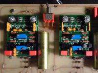
Line modules finished
Eventually I finished the line modules. Many thanks to Erno Borbely who was very helpful
and sent me matched quads of 2SJ74V and 2SK170Vs. He also has the other parts in stock
and much more. Very recommended.
Attached is the final schematic I used. I´ve built a version with Fairchild
2SA1381 / 2SC3503 for test purposes too, seems to work equally well.
Attachments

Very nice modules, GK7
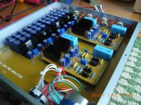
Recently, I also built a new JC-2 line stage with the following modifications:
- new power supply based on JC's published on the Positive Feedback magazine in 1998
- parallel total 4 pairs JFets per each channel
- increased the power rails from +/- 15v to +/- 24v
Recently, I also built a new JC-2 line stage with the following modifications:
- new power supply based on JC's published on the Positive Feedback magazine in 1998
- parallel total 4 pairs JFets per each channel
- increased the power rails from +/- 15v to +/- 24v
Attachments
Nice work! I'd like to see the measurements.
Don´t expect too much from the measurements, the distortion
of this circuit is fairly low. When making a spectrum analysis
of the original modules using my RME ADI-2 (AD and DA converter)
the results were only marginally different compared to the RME only.
So unless something is fundamentally wrong with the new modules there
will not be much to be seen. But maybe I can improve the measurement
setup somewhat.
Recently, I also built a new JC-2 line stage
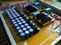
That looks great ! How much current do you run ?
Is that a Penny & Giles Potentiometer ? Where did you buy one ?
That looks great ! How much current do you run ?
Is that a Penny & Giles Potentiometer ? Where did you buy one ?
I am running 10.6ma input and 50ma output.
Yes it is a Penny & Giles 10K potentiometer, I bought it in Hong Kong.
Attachments

very nice work!
although, it does look a bit strange to see that nice penny and giles pot next to that rotary switch. 😱
mlloyd1
although, it does look a bit strange to see that nice penny and giles pot next to that rotary switch. 😱
mlloyd1
Thanks John for open the circuit to the public. It is a classic and simple pre-amp circuit and a I have lot of fun from it.
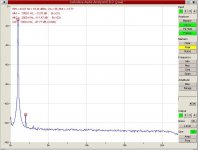
Did some quick measurements recently but as mentioned in post #192
the picture on the (software) analyzer is essentially the same as
that of the D/A -> A/D loop alone. I probably would need a notch filter
to null out the fundamental or if this is not sufficent a lower distortion
source too. Therefore I only post one picture as an example.
But the good news certainly is the line modules do not add extra distortion
to the lowest distortion source I have in my system while adding gain - who
could ask for more.
The 2nd is at -97.77dB (0.0013%) and the 3rd at -109.12dB (0.0003%)
(mesured approximately the same values for the RME ADI-2 D/A A/D converter alone)
The was connected to a RME Digi96 digital i/o card on a linux system.
The ADI-2 inputs and outputs where set to +4dBu.
The software used is jaaa ( Kokkini Zita - Linux Audio interesting
website BTW if you use Linux) which contains a sine generator and a FFT analyzer.
If someone knows a good schematic for a notch filter (yes I know there can
tons of them be found on the net - but it should have sufficient low distortion)
please advise. An AP unfortunatly is not supported by my wallet...
Attachments
well done GK7
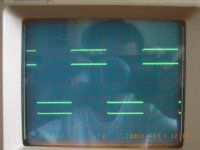
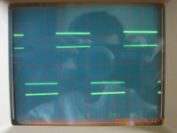
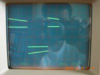
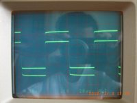
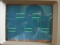
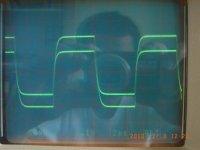
I also measured the sq wave form of my JC-2 in the following order:
20Hz
100Hz
1KHz
10KHz
50KHz
100KHz
It was my first time using a oscilloscope. Please comment.
I also measured the sq wave form of my JC-2 in the following order:
20Hz
100Hz
1KHz
10KHz
50KHz
100KHz
It was my first time using a oscilloscope. Please comment.
Attachments
- Home
- Source & Line
- Analog Line Level
- Need to build JC 2 preamp