If that power supply is 'horrible sounding' then most audio equipment in the world shares its fate.
The real question is: "What does a power supply do?"
The real question is: "What does a power supply do?"
john curl said:"What does a power supply do?"
If you don’t know what a power supply do I can’t help you, maybe nobody can.
Cheers
Stinius
Look, I'm the 'instructor' here! I will have to send you to the principal, if you continue to talk back.
I have found that a power supply cannot be all things to all people.
It is like designing a 4 wheel drive vehicle that can also cross a lake on its own, and be entered into a road race. It is an interesting design challenge, but it is nearly impossible.
Now, to me, the first thing that a power supply has to do is to regulate pulsating DC to non-pulsating DC and set a nominal DC voltage. That is about all that the LM317-337 does really well. The rest depends on following circuits, AND capacitors.
john curl said:If that power supply is 'horrible sounding' then most audio equipment in the world shares its fate.
The real question is: "What does a power supply do?"
What it should do: DC with low impedance across the audio band and beyond
- sounds easy but is difficult.
john curl said:Look, I'm the 'instructor' here! I will have to send you to the principal, if you continue to talk back.
Sorry Sir I promise I will never do it again.
Attachments

john curl said:I have found that a power supply cannot be all things to all people.
It is like designing a 4 wheel drive vehicle that can also cross a lake on its own, and be entered into a road race.
<snip>
Now, to me, the first thing that a power supply has to do is to regulate pulsating DC to non-pulsating DC and set a nominal DC voltage.
What? No more Porsche?
And the rest? Noise, RF ingress, etc...? Out of the blue these are non issues? BTW, LM337 has less than 30dB ripple rejection at > 100KHz. And the load and line transient responses (something you just mentioned these days as being critical) are absolutely horrendous, e.g. +/-0.6V output voltage transients for a +/-1V line voltage step. See the data sheet (DOH!).
gk7 said:and for those who think the power supply is to simple, here is something cooked "a la Walt Jung" (stolen (whith minor modifications) from his book OpAmp applications).
C'mon, that's a dual tracking variable power supply - you certainly don't need that.
Here's a link to the Jung regulator, you can further simplify the schematic to adapt to your (less demanding) requirements. You may simplify the current sources (perhaps use a cheap JFET), you may not need the startup schema (if you adopt an earlier version of the same regulator) etc...
http://waltjung.org/PDFs/Improved_PN_Regs.pdf
don't we all think the powersupply must be faster than the amp
otherwise It's just wrong
please shoot me
regards
Max
otherwise It's just wrong
please shoot me
regards
Max
syn08 said:
C'mon, that's a dual tracking variable power supply - you certainly don't need that.
Here's a link to the Jung regulator, you can further simplify the schematic to adapt to your (less demanding) requirements. You may simplify the current sources (perhaps use a cheap JFET), you may not need the startup schema (if you adopt an earlier version of the same regulator) etc...
http://waltjung.org/PDFs/Improved_PN_Regs.pdf
I know the link and the schematic is from 1997 (no "cheap FET" at that time).
BTW it works quit good. But if you present something better you are welcome.
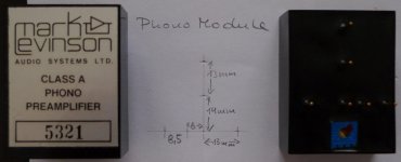
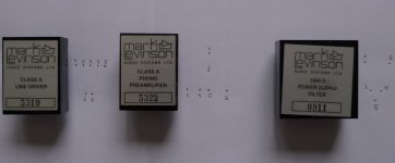
I have deliberately assigned numbers to the pins (see attachment).
Line Driver:
1 not connected
2 OUT
3 V- (-17V)
4 GND
5 V+ (+17V)
6 + IN
7 - IN
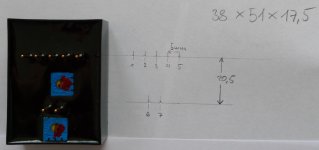
Phono:
1 + IN
2 V+ (+15V)
3 V- (-15V)
4 - IN
5 OUT
6 GND
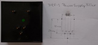
Power Supply Filter:
1 -V out (-15V)
2 +V out (+15V)
3 -V in (-17V)
4 +V in (+17V)
5 GND
Line Driver:
1 not connected
2 OUT
3 V- (-17V)
4 GND
5 V+ (+17V)
6 + IN
7 - IN
Phono:
1 + IN
2 V+ (+15V)
3 V- (-15V)
4 - IN
5 OUT
6 GND
Power Supply Filter:
1 -V out (-15V)
2 +V out (+15V)
3 -V in (-17V)
4 +V in (+17V)
5 GND
Attachments
other photos
I think I will place the rest of the photos on my homepage on monday and post the link here because they are more instructive in high resolution.
I think I will place the rest of the photos on my homepage on monday and post the link here because they are more instructive in high resolution.
Re: other photos
Hi gk7
Very well done. I am looking forward to see the link of your homepage.
Thanks
gk7 said:I think I will place the rest of the photos on my homepage on monday and post the link here because they are more instructive in high resolution.
Hi gk7
Very well done. I am looking forward to see the link of your homepage.
Thanks
If have placed the photos I made from the JC-2s inside here (they include a link to download the full resolution original too:
http://hal9000.at/JC-2/index.html
Capacitor replacement:
I refer to the part numbers used in the attached schematic.
C18a C18b (left and right) will be replaced by wire. In my ML-1 they are located on the copper side of the mainboard.
C16a, C16b, C19a and C19b will be replaced by polypropylene capacitors. These caps could be placed on the copper side (maximum diameter is then 15mm) or on top where the maximum diameter would be 20mm except for C19b which is between one line module and the power supply filter. This placement only allows for 14mm diameter.
Maximum length is 45mm.
Space limitations rule out most "boutique" capacitors.
These I use: Vishay-Roederstein MKP-1839 with 160 VDC
4.7 uF (41.5mm x 15.5mm) for C16a, C16b and
2.2 uF (31.5mm x 13mm) for C19a, C19b
Attachments
- Home
- Source & Line
- Analog Line Level
- Need to build JC 2 preamp