I've measured probably thousands, I used to work at a transformer manufacturer.
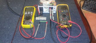
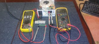
This is a particularly well designed transformer, looks about 300VA with very low core losses.
On the left with approx 25W light bulb load = 114 mA. On the right we have a massive 9 mA no load current.
Note I am measuring AC voltage across a 1 ohm resistor so there is no discrepancy, my current monitor attached to the Variac that is feeding this gets a bit flaky at these low currents.
If I wind the no load prim voltage up the core saturation current knee is quite high at over 260 V, it's a VG transformer.
If I measure a less efficient EI core transformer with a cheaper non grain oriented core (Toroid uses GOSS) the no load current will be higher, sometimes significantly so.
Terry
Attachments
Last edited:
Just measured an Antek AN-0109 transformer and with no load on the secondary at 120.3V (variac adjusted), both current and VA/W rating were unmeasurable on my kill-a-watt meter. (Resolution 10mA and 0.1VA/W) I thought the meter was broken so confirmed it with another device, and found it was working normally. I also confirmed the transformer was OK by measuring secondary voltage and applying a load resistance.
Terry's comments are consistent with my own experience, and I did design a few power transformers over the course of my ongoing career with third party transformer makers which behaved exactly as he has described in previous posts and demonstrated clearly in the preceding post.
If there is any interest I can duplicate his experiment tonight, but don't think it is necessary.
UPDATE: I hooked up the 250 VA transformer, ran it for 12 hours and it got pretty hot. I then disconnected it from the lift all together and left it plugged in. It remained just as hot. I called the company ands talked with a tech support guy who sounded like he knew less than most of the guys here. He said the heat is fine and the transformer can be used for continuous duty. We'll see.
The plan is to keep using the 250 VA transformer. If it has no issue, I'll permanently incorporate it into the lift. If not .... it's back to the drawing board.
I got a call back from the lift sales person who was going to look into this for me. Not any help. He suggested changing the relays. I guess he didn't understand the issue ... plus, all the relays have been changed.
The second lift he wants to sell me is a used unit, identical to the first! If I go with this one I'm going to do what someone at the beginning of this thread suggested, a 3-way switch set up, one switch at the top and one at the bottom, that turns power on and off to the unit. I'll incorporated a light somewhere for when the lift is on so people remember to switch it off (Hopefully).
It seems like there are a few here very knowledgeable about transformers. Does this heat issue sound normal for the new 250 VA unit when there is absolutely no load on it?
Thanks,
Eric

I would just go with a better transformer and a primary fuse for protection, can just be left on. Try the Antek, it's cheap and might solve the problem.
Have you confirmed that the transformer is actually unloaded when the lift switch is "OFF" I see you ran it disconnected, so how hot is "hot" ? External temperatures of up to 65°C (149°F) are considered acceptable in operation, but any transformer that gets that hot during unloaded operation is one I would avoid in a world of ever increasing energy costs. (inefficient & excessive transformer losses IMO)
Have you confirmed that the transformer is actually unloaded when the lift switch is "OFF" I see you ran it disconnected, so how hot is "hot" ? External temperatures of up to 65°C (149°F) are considered acceptable in operation, but any transformer that gets that hot during unloaded operation is one I would avoid in a world of ever increasing energy costs. (inefficient & excessive transformer losses IMO)
I would try the transformer on a 24V / 10W tail lamp bulb, and see the rise after an hour or so.
5 C above ambient is okay, more is not acceptable.
The circuit seems the switches for the box doors and top / bottom doors are in series, if any one is open the contactor / relay coils will not get power.
So in normal condition (all on), the relays are powered (or not), and it is the passenger's choice to engage the AC motor to up and down.
I think an AC side switch would be a good idea. Safer, and no wasted energy.
If it is a toroid, should it be mounted with a center bolt, or that is not necessary during testing?
For testing no mounting bolt is required, what is important is that there be nothing that looks magnetically like a shorted turn passing through the center of the toroid, metal covers for example should not be allowed to touch the chassis if a metal mounting bolt is used. Some covers are non-conductive anodize while others are a mm or so above the chassis when installed properly. One in an application like this would not be covered.
I use a lot of toroids in my projects, and particularly like Antek, Talema and Amveco toroids. (I also have developed a preference for some of the Chinese made R core transformers and use them frequently too.
I use a lot of toroids in my projects, and particularly like Antek, Talema and Amveco toroids. (I also have developed a preference for some of the Chinese made R core transformers and use them frequently too.
Oh, another thing, switches may be having poor contacts, check with a meter, power off of course.
And see if the relays are held as NC, some magnetic clutches and brakes have that for safety. They are held closed. so the machine will stay locked when there is no power, that is done by springs.
And check the motor drive for friction with power off, that will give you some idea about overall build quality.
It seems to be using too much power during stand by, maybe we can modify the circuit to improve it while meeting safety standards.
But you did say the company employee said this was a common problem...could be a bad design to start with, minimally meeting standards for safety.
Looks like there is ongoing confusion about how the motor is powered. A schematic might be very helpful for readers following this thread.
I think the power to the AC motor is through the magnetic relays / contactors, whose coils are low voltage AC.
Motor is at mains voltage.
Motor is at mains voltage.
The transformer in the control box is a energy limiting transformer ( for safety) to control a few relay/contactor for the lifer motor, it only draw 0.58A when the switch is on and the lift is in operation. The problem of OP's lifer is the transformer draw excessive idle current and overheated that need to reset regularly.
Perhaps a high temperature design energy limiting transformer like the Hammond BE2G (105 degree) might solve the problem.
https://www.mouser.com/Hammond-Manufacturing/BE2G
Perhaps a high temperature design energy limiting transformer like the Hammond BE2G (105 degree) might solve the problem.
https://www.mouser.com/Hammond-Manufacturing/BE2G
Last edited:
"metal covers for example should not be allowed to touch the chassis if a metal mounting bolt is used." I might be misunderstanding this. Are you saying the metal bolt securing a toroidal transformer needs to be isolated from the chassis? I have a handful of Threshold power amps which use toroidals and the center mounting bolt passes right through the metal bottom of the chassis.
Just to clarify, there is a switch directly after the secondary that can be manually turned off. When the lift is not in use, this switch is turned off. Thus, the secondary goes no where, does nothing, has not load. I have checked the switch to make sure it is not remaining closed when it is placed in the open position. I have even disconnected the wire from the secondary and put wire nuts on those wires just to make sure they don't touch anything and the transfomer is still getting hot and the primary pulling current (see above). The original would overheat and as of now the 250 VA just gets pretty darn hot. There are no mystery wires or electronics coming off of the secondary before the switch that I am overlooking.
I'm going to skip drawing a schematic at this point as I think we have isolated the problem to the transformer. I'm not sure if a drawing showing a switch in the open position directly after the secondary windings is any more descript than the paragraph above.
I like the idea of the High temp. Hammond or Toroidal transformers. I think the original transformer is not meant for continuous duty use and there rests this issue .... so I think! If the 250 VA unit works, I'll measure the draw on that. If it's high, I might switch to the Hammond or the Toroidal type just to see how they work and if they draw less current in idle the the 250 VA unit.
Question: Would the toroidal design draw less current at idle than the traditional (Hammond) type? If a different transformer is the solution, then choosing one that is more efficient would be the next step.
Yes, If the second lift ends up being like the first, I'll probably do the 3 way switch so power is shut off to the lift all together when not in use. I'll avoid this issue and save energy.
Thanks,
Eric
Thanks. I never would have guessed that.One end of the toroid bolt can touch the chassis, but not both ends at the same time.
That would constitute a shorted turn.
Eric
And to avoid shorted turn issues, the non touching end should be a little away from the metal housing, the more experienced members will tell you that...
I think a circuit which is just powering a few magnetic coils through limit switches should not draw so much current.
As an experiment, please take the supplied small transformer, check its coil resistance, and see how much the idle current off load actually is.
Then check it on a low load, like a 24V truck lamp, to bring the power factor and regulation more in line with actual conditions.
A clip on digital clamp meter or plug in power indicator will come in handy.
It will tell you whether it is a transformer problem, or something is wrong with the components.
The coils should draw less than 10 watts, and that is when activated, zero in off condition.
So what is causing the load that makes it hot?
Is the primary coil being used in series with the motor as a current limiter?
Even that (a wrong design, I think), should not cause a high idle current.
Just for your information, Hammond Manufacturing also make a energy limiting, 24V 40VA plug-in style transformer BPE2G, made installation quick and easy!
https://www.mouser.com/Hammond-Manufacturing/BPE2G
https://www.mouser.com/Hammond-Manufacturing/BPE2G
This is a bit like the computer speakers with the power switch on the secondary side, the transformer stays on, average user does not know, as the LED is off, and the cheap transformer blows sooner or later due to heat.
Then I had to replace the transformers, and short the switches.
Last one was a beefy wall wart, with LED indicator.
Supply after the rectifier for the chip amp, as the rectifier and cap were in the wall wart.
Easy to replace, and the user knows it is on power.
Beefy means less sag on load.
Best that the mains power is switched on only when needed.
The main switch will be easy to access even at the high point, travel in this case is only 21 inches.
That will make the thing reliable, which I think is important.
The one item here that needs current limiting is the drive motor, any overload switch, those are common in the refrigeration / Air conditioning field, will achieve that object.
And a fuse can be used for secondary side.
Unless there is a legal requirement, I see no need for a current limiting transformer.
Last edited:
Easy test. Measure the unloaded primary current. Remove the bolts holding the covers on the transformer. Space the covers a slight bit off the transformer core. Now measure the primary current again.
The bolts are needed to keep things together. If the current does drop then use smaller diameter bolts and insulating washers. I would not change them to plastic as that would reduce fire protection. However as there are six places to bolt the covers if you do want to use nylon bolts instead use all six positions. After changing the cover attachment measure the primary draw again. You might have to add fish paper under one cover side.
https://www.americanmicroinc.com/electrical-insulator-materials/fish-paper/
Last edited:
- Home
- General Interest
- Everything Else
- Need Some Advice Regarding a Handicap Lift, Odd Transformer Issue