The current in a practical power transformer is actually quite constant from no load to full load. It is the phase angle between the current and voltage that changes. So unloaded the power drawn is actually low.
If there is a significant load it is worthwhile to install power factor correction capacitors to reduce the power actually drawn from the source.
In large venue sound systems, before switching power supplies, the cost savings from adding the capacitors would often have a payback time under a year! (Figure 100 three hour events per year VS the thousands of hours drawing current but not power! The utility has to provide the current which they charge for!)
In a system for the handicapped I suspect a thermal cutoff is mandatory.
"A bigger transformer could turn out to be worse". Yep, we'll know soon.
"A quicker and very cheap experiment would be to get an Antek toroid" I like that idea. If the bigger transformer doesn't work, I'll give that a try.
"First check the AC outlets" 117.5 vac, see above
Thanks all.
"A quicker and very cheap experiment would be to get an Antek toroid" I like that idea. If the bigger transformer doesn't work, I'll give that a try.
"First check the AC outlets" 117.5 vac, see above
Thanks all.
Could be the motor itself.
Most single phase AC motors use a "run" capacitor to create the phase shift needed for rotation.
When capacitor goes bad, the motor may start but will run slower than it should and run hot under load.
The motor may also be thermally protected with an internal, resetable device, so when it over heats it will shut off and then work again after it cools.
Check the value of the capacitor.
Remember, the motor is not part of the failing 24 vac issue, it's 120 vac. And the problem happens while everything is off, no motor running, relays off, secondary switched off. The motor does not run off of the 24 vac secondary from the transformer, the transformer only operates the relays.
120V x 0.42A = 50.4WattThe current draw at the 120 vac primary is .42 amps when the secondary is unloaded, the switch right at the secondary output turned off.
That increases to .58 amps when the switch is on and the lift is in operation.
wasted 44kwh per year!
Your existing transformer is rate 40VA, it expected to be overheat!
I like the idea of remotely switching its primary instead of secondary winding. It save a lot of money 24/7/365 and no need to replace transformer regularly.

What is the load on the transformer?
As you say, just the control circuit, and with relays off, it is still taking a lot of current...
Check it closely, possibly bad components on the DC side, replace if within your skill set.
The company man says it is a common problem, so somebody cheaped out, maybe a contract supplier was told to reduce price.
And you can see the result.
The price difference between a 60VA and a 40VA unit is in pennies (bulk purchase).
Please refrain from buying another unit from the same supplier, the rest of it is likely to be of poor quality, ask or look around for better made competitors.
Sorry, this is not correct at all. A well designed transformer will have a very low, no load primary current.The current in a practical power transformer is actually quite constant from no load to full load. It is the phase angle between the current and voltage that changes. So unloaded the power drawn is actually low.
The main cause of excessive prim no load current is core saturation / losses due to a/ too high prim voltage b/ cheap core material.
Possibly you confused IP current with core magnetization level which does does not vary between loaded and unloaded.
Terry
Some people coming late to this thread may not know that the transformer in question is not exactly a typical transformer.
Specific transformer being used in described at: https://www.supplyhouse.com/sh/control/product/~product_id=90-T40F3
A catalog listing of the transformer describes a bit more about it: https://s3.amazonaws.com/s3.supplyhouse.com/product_files/White Rodgers - 90-T40F3 - Brochure.pdf
Given that is it an "energy limiting" and or maybe a "current limiting" design, its leakage current and or self-heating may be different from other types of transformers.
In brief, one main point is the transformer is intended for particular uses: "For Industrial, Heating and Air Conditioning Controls Applications"
One may ask, "why is the transformer intended for those specific applications?" Maybe also ask, "what exactly is an energy limiting transformer, and how is it different from an ordinary transformer?"
Maybe taking a look at the attachment to #16 would be helpful.
Last edited:
Edited / deletedOK, the secondary voltage is 28.15 vac unloaded, the switch right at the secondary output turned off.
The voltage remains the same when the switch is on.
The voltage drops to 27.5 vac when the lift is in operation (All the secondary does operate relays)
The current draw at the 120 vac primary is .42 amps when the secondary is unloaded, the switch right at the secondary output turned off.
That increases to .58 amps when the switch is on and the lift is in operation.
Last edited:
I have a water pump controller, a 4066 IC checks the four float switch levels, controls a transistor, which controls a relay, that switches the pump on and off.
The supply is a 200mA transformer, 4 diodes in a bridge and a smoothing cap.
It stays on all the time, and gets barely warm in 45 C heat.
IMO, bad quality somewhere, in design or execution, in your unit.
As a pointer, see horror stories of price competition in the auto parts and chain shops (ie large chains, for example Wal-Mart) businesses...
44 kWh x $0.3 is 13.2 Dollars, or a burger with accompaniments in annual energy wasted.
That is less important than the fact that this is for handicap use, must work fail safe in an emergency situation.
Bear that in mind, as you proceed.
Last edited:
Thanks Mark.Some people coming late to this thread may not know that the transformer in question is not exactly a typical transformer.
Specific transformer being used in described at: https://www.supplyhouse.com/sh/control/product/~product_id=90-T40F3
A catalog listing of the transformer describes a bit more about it: https://s3.amazonaws.com/s3.supplyhouse.com/product_files/White Rodgers - 90-T40F3 - Brochure.pdf
Given that is it an "energy limiting" and or maybe a "current limiting" design, its leakage current and or self-heating may be different from other types of transformers. In brief, one main point is the transformer is intended for particular uses: "For Industrial, Heating and Air Conditioning Controls Applications"
One may ask, "why is the transformer intended for those specific applications?" Maybe also ask, "what exactly is an energy limiting transformer, and how is it different from an ordinary transformer?"
Energy limiting will generally imply some combination of either core saturation with high leakage inductance (prim -> sec coupling) to result in a either a short circuit proof or certain over current-proof design.
Looking at the data sheet, it's a split bobbing design (higher leakage inductance) and non interleaved / welded laminations, maybe gapped.
That will indeed result in a lower efficiency and high no load current. It's a pity the data sheet doesn't include some real specs for no load current, regulation etc.
Are you saying it needs to be able lower someone from upstairs on battery backup power in a power failure emergency?That is less important than the fact that this is for handicap use, must work fail safe in an emergency situation.
Bear that in mind, as you proceed.
It could be a requirement, but it seems to be not important as in the video, easy enough for a fireman or EMT to lift somebody 21 inches.
The thing is that it should be an instinctive design, in that some things must always be part of the design, should not fail.
If the person is alone, for example, and the patient needs to go to the bathroom, and it is broken. That will be a problem.
Or I can say it must work all the time.
The thing is that it should be an instinctive design, in that some things must always be part of the design, should not fail.
If the person is alone, for example, and the patient needs to go to the bathroom, and it is broken. That will be a problem.
Or I can say it must work all the time.
"Try checking the voltage on a few more outlets." Checked a few other outlets in the house. All within about 1 volt of the plug this unit is plugged into.
"Check it closely, possibly bad components on the DC side," No DC in any of this. It's all AC, 120 volt or 24 volt (well, 27.5 volts!)
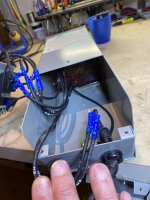
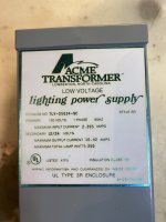
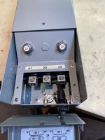
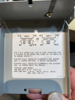
Attached are pictures of the 250 VA transformer I'll be installing. It's an exterior landscape light transformer that has breakers on the secondary, I'm not sure what sort of thermal protection it uses. The transformer is incased in some sort of "epoxy", all you see are the wires coming out. I'll hook it up tonight and report back if it's getting hot or not.
Thanks for all the help.
"Check it closely, possibly bad components on the DC side," No DC in any of this. It's all AC, 120 volt or 24 volt (well, 27.5 volts!)
Attached are pictures of the 250 VA transformer I'll be installing. It's an exterior landscape light transformer that has breakers on the secondary, I'm not sure what sort of thermal protection it uses. The transformer is incased in some sort of "epoxy", all you see are the wires coming out. I'll hook it up tonight and report back if it's getting hot or not.
Thanks for all the help.
Attachments
It needs 4 inches clearance on all sides in indoor installation.
Maybe that means it needs a larger enclosure?
The more experienced members' advice should be taken.
Maybe that means it needs a larger enclosure?
The more experienced members' advice should be taken.
The more I think about this the more I feel this transformer is just a poor design probably not meant for continuous duty use. It draws more than it's rating with no load on the secondary. It can do that for a month before needing a 12 hour break to cool down. What more could it be with just the primary hooked up and the secondary open? This is a brand new transformer .... although the old one did the same thing, maybe lasted 2 months before needing a cool down period.
I wonder how this landscape transformer will hold up? I'm sure the idea is the primary is switched on / off to operate low voltage lights and I imagine that's probably not more than 12 hours at a time. Hopefully this transformer will do better with no load considering it's designed to run at least 12 hours with a 10 amp load on the secondary.
How do all these preamps work with remote power supplies that are always plugged in? I'm thinking about the Threshold FET series from the 80's as well as things like the PS Audio IV. I had a PS Audio IV preamp power supply plugged in for probably 20 years straight. It had a transformer right off of the line and there was no power switch, you would turn the DC power from that supply on or off at the preamp. With some of the Threshold gear, wasn't the power button on the preamp just a mute button? The idea was all the components had power to them all the time so there was never any "warm up" time. How come those preamp power supply transformers lasted 20 years and I can't get 2 months out of my lift transformer!?
Maybe Nelson Pass or Paul McGowan should think about designing handicap lifts 😊
"Maybe that means it needs a larger enclosure?" This thing is too big to fit in the housing. If it works, I have a plan for permanent wiring, but it will probably be surface mounted on the side of the lift since it has it's own housing. For now (and probably the next 2 - 3 months, if it keeps working), it's just sitting on the floor with plenty of clearance and a 16 gauge wiring running to the unit.
Fingers crossed.
Fingers crossed.
Take care, you have children, who look old enough, and maybe pets in the house.
They have used 27V AC for the safety interlocks, like door switches.
I would have used proximity switches and 4000 series gate chips.
And in India, the reverse forward switch from a lathe, or a push button station.
This is a variant of goods lifts used in warehouses, without the duct or shaft.
They have used 27V AC for the safety interlocks, like door switches.
I would have used proximity switches and 4000 series gate chips.
And in India, the reverse forward switch from a lathe, or a push button station.
This is a variant of goods lifts used in warehouses, without the duct or shaft.
Go measure one! An unloaded transformer is an inductor. That puts the current and voltage almost completely out of phase.Sorry, this is not correct at all. A well designed transformer will have a very low, no load primary current.
The main cause of excessive prim no load current is core saturation / losses due to a/ too high prim voltage b/ cheap core material.
Possibly you confused IP current with core magnetization level which does does not vary between loaded and unloaded.
Terry
That is why the OP is seeing such high unloaded current. Not to be confused with the power wasted.
There is a reason that power factor is measured and billed in commercial installations.
I suspect you were taught about magnetizing current from a textbook and never actually measured it. It was a big surprise to me the first time I started measuring current draw. When was the last time you designed a transformer?
Last edited:
- Home
- General Interest
- Everything Else
- Need Some Advice Regarding a Handicap Lift, Odd Transformer Issue