I created my own frd and zma files from the pdfs for the XO I knocked up, but have since deleted it Summed response was flat as a pancake, honest.
Anyhoos, I may try to reconstruct it later.
The tweeter has a naturally sharper rolloff than a shallow slope; try 3rd order, try 4th order.
It might have been Xsim doing something weird.

As far as I know people used the FRD consortium's programs to do this.
FRD Consortium
the baffle diffraction simulator and FRD combiner or something.
Those are only available on the waybackmachine archive thing linked above.
Then again the thread that details speaker design without measurements must also have a way of doing this. I'd read that thread and see what it talks about. I haven't given a huge amount of attention to crossover design without measurements, as I simply measure everything I build, but adding diffraction and simulating/creating a decent phase response for the two drivers is vital to a good design.

Must be a discrepancy in the tweeter FRD files; can you compare vs my last attachment zip?
Edit: it's the ZMA file values; yours are wrong (too low, e.g. 200hz = 3ohm, datasheet and my file = 5ohm, and so on)
Edit: it's the ZMA file values; yours are wrong (too low, e.g. 200hz = 3ohm, datasheet and my file = 5ohm, and so on)
Last edited:

You can just use my files in the zip above 😎 - tip, try using VituixCAD's "SPL Trace" tool option - it's better than FPGraphTracer.
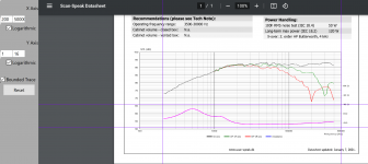
Yes. I don't think FPGraphTracer is gonna be able to properly trace this. The issue is FPGraphTracer has options for linear or logarithmic scales. Scanspeak's datasheet for impedance is neither linear nor logarithmic. Why would they do that! That's just cruel.
I see the markings are log but what made no sense to me is that counting from zero there are 4 spaces to the 4 ohm mark, 10 to the 8 ohm mark, and 16 to the 16 ohm mark. I cannot use the 4 ohm mark as a border because the impedance dips below that. I'm sure there's a way to do it I just don't know how lol. It's been a long day. I will use your data.
You can use any two marks and the software interpolates all other points referencing those points
I should probably post this in the fpgraphtracer thread. But this is what I'm doing and it still ends up being quite different than yours. Changes the response quite dramatically. I also tried setting lower limit at zero and inputting .0001 ohms (as setting zero gives an error) and it's even worse.
Attachments
Either way, your crossover looks quite good, I just need to put in some baffle step compensation.
your lower bar is not "1" - ignore all horizontal lines except the explicitly marked values, e.g. 4ohm
well, thanks, experiment also with say a 2.5k xo point, and tweaking the right-hand curve overall down a little (most people prefer a small-ish tilt down towards higher frequencies)
well, thanks, experiment also with say a 2.5k xo point, and tweaking the right-hand curve overall down a little (most people prefer a small-ish tilt down towards higher frequencies)
I realize that the lower bar is not 1. But the only other options I have are 0 and 4. 4 won't work. 0 wont work. 0.0001 wont work!
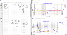
Anyways. I used the late Jeff Bagby's baffle diffraction spreadsheet to have a look at the baffle step in my cabinet and added a baffle step circuit. It of course caused changes in the response so I had to change a lot of the values. The 4.5khz resonance is still there but it's 25db down so I'm thinking won't be audible. The crossover point is 2khz but the slope looks like near 4th order acoustic to me so I'm happy with that.
Edit: I left the slight rise in tweeter response on purpose. I'm not afraid to leave a slight "v' curve in the response. But I can easily tilt it down by adjusting C3.
Attachments
Last edited:
How it look with tweeter reversed?
Inverting the tweeter polarity creates a 5db dip at x-over frequency.

Well that did it. Knocked out the woofer resonance. What did you do?
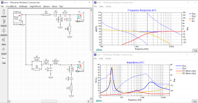
I changed C5 to 2.7uF to bring the x-over frequency from 1.8khz to 2.2khz and to increase the tweeter slope from 16 up to about 20db/octave. Also added in BSC which required adjusting R3 and C3. The rest of the values I left as you set them. Thanks!!
I changed C5 to 2.7uF to bring the x-over frequency from 1.8khz to 2.2khz and to increase the tweeter slope from 16 up to about 20db/octave. Also added in BSC which required adjusting R3 and C3. The rest of the values I left as you set them. Thanks!!
Attachments
Last edited:
- Home
- Loudspeakers
- Multi-Way
- Need help with crossover for Phenomax midwoofer and 3/4" Revelator