Everything is wrong with these circuits. Sorry. Crossover far too low. Impedance is terrible. Capacitors way too big.
You need impedance correction on the midbass. A notch around 4.5 or 5 kHz. Higher crossover. No way the bass coil arrangement should exceed 2mH in total. Trust me.
Ok. But I'm still not understanding how applying a crossover designed for different drivers makes any sense. Plus no, I can't afford to get another tweeter right now. Besides, I don't want to use the CAT378. Why would I? I have a pair of Revelators right here.
You won't be using Mike's crossover. But you will be using his ideas for how to deal with a Scan 5" midbass with a horrible peak around 5kHz. A bit of help with the box too.
He employs essentially a single capacitor on the tweeter for shallow slopes. I can't give out his intellectual property. But your tweeter is less suitable for a shallow slope. Might be possible though.
One Scan 5" is much the same as another. I'm not going to model it, but you can. Changing to 8 ohms from 4 ohms is simple enough. Bigger coils and resistors, smaller capacitors. I have slight doubts if your tweeter level is right as well. I would expect more attenuation, and better applied for good impedance.
I thought I may just add in to this have the traced frequency responses been processed to take into consideration baffle diffraction and the acoustic/phase offset between the two drivers?
I've loaded up the FRD/ZMA files and they appear to be completely raw.
I've loaded up the FRD/ZMA files and they appear to be completely raw.
It was a simple exercise for me to show that is possible to obtain the same shape with less components. Only 15 minutes and I was sure that the crossover frequency is too low. But if you want only a computer speakers, soo low power, can work.
Mr Chua's crossover is 16 components! But he has reasons for needing a couple of notches that I fully approve of. First order is often more complicated than higher orders.
These will be used in room, not for a computer. So anywhere from near to far field. The boxes have already been built, as have the aluminum baffles. I had them machined for me at my father's shop. So none of that is going to be changed.
I have not taken into account the baffle diffraction and acoustic offset. I'm not sure how to do that without first measuring the drivers in-box. I'll have a read through the thread on designing crossovers without measuring.
I'm also not sure what the power response looks like. I'd be particularly interested in knowing what it's doing 60 degrees off axis. But until I get measuring equipment I'm SOL.
It'll do what it does off-axis. You are kind of stuck with that, though 90 degree Butterworth phase can fill the off-axis dip a lot.
Off the top of my head, I would guess the 5" woofer acoustic centre is about 15mm behind the tweeter. This is often fudged with a higher order on the tweeter, which delays the sound more.
1-2mH inductance on the bass should get you near the right bafflestep. Not really too critical for, say, a 6 or 7" wide box.
Last edited:
1-2mH inductance on the bass should get you near the right bafflestep. Not really too critical for, say, a 6 or 7" wide box.
Today 05:17 PM
From my understanding, 5th Element was referring to baffle diffraction in regards to the tweeter, not baffle step. If you look at my crossover I have baffle step compensation in there.
He was probably referring to step loss, so the woofer.
I think both these drivers are not the easiest to deal with; I mocked up a 4th order acoustic (3rd order electrical) @ 2.8khz based on the spec sheets; to keep some distance from the woofer breakup and move the tweeter closer to its distortion sweet spot (measurements on HFC here)

I think both these drivers are not the easiest to deal with; I mocked up a 4th order acoustic (3rd order electrical) @ 2.8khz based on the spec sheets; to keep some distance from the woofer breakup and move the tweeter closer to its distortion sweet spot (measurements on HFC here)
Thanks Motokok, that's much appreciated. However I would like it if someone would actually look at my crossover and tell me what's wrong with it that I need to use someone else's. Maybe I should have made the title "rate my crossover".
(measurements on HFC here)
Now that's interesting. There appear to be two different versions of the 3/4" revelator. The one on the hificompass site has a replaceable dome/coil assembly. Mine does not. The one on their site also appears to have a thicker faceplate than mine. This would explain why the tweeter recess on the aluminum baffle I had machined directly from Scanspeak's data sheet is too deep, and I still have to add a layer of something to make it flush. I thought they had just made a mistake on the drawing but nope! Guess not.
Makes me wonder if they are cheaping out for the North American market. I'll be emailing Scan-Speak about this.
I doubt it; Scan is a highly reputable company and that sort of business-practice isn't the kind of thing they are known for (to say nothing of the dodgy economies of scale it would introduce). More likely, they changed the design a little between pre-production prototypes / a pre-production run, and neglected to update some of the published data. Annoying, but unfortunately that sort of thing does happen from time to time, without intent.
Be that as it may -as has been noted, you've got a bit of a mismatch in the nature of your drivers -a midbass that isn't really too great at the top end, and a 3/4in dome tweeter that can't really be taken particularly low since like most small domes, its distortion performance isn't stellar, especially at low frequencies.
On a quick look, you'll probably need something like asymmetric LR4 (acoustical) in the 2.5KHz region. The tweeter really doesn't like going lower than that, & ideally would be better crossed higher, but you've the midbass breakup to deal with. 1st & 2nd order are realistically out; 3rd order Butterworth might work if you don't mind the lobing in the polars, but it puts more stress on the drivers at a given XO frequency as it crosses at -3dB rather than the -6dB of a Linkwitz or variation thereof. Quasi-LR3 (i.e. 3rd order acoustical crossing at -6dB) may work -the driver offsets on a flat baffle can help bring things into line, even though it may not look great assuming common acoustic centres. Chances are you'll need at least 3rd order electrical on the tweeter, plus level padding & a damping shunt resistor (an Fs LCR may be preferable). Midbass may be OK with 2nd order electrical & a tank notch on the primary. Possibly. Depends on how the phase lines up & what the distortion is like through its passband (i.e. how much is amplified by the ~4.5KHz stopband breakup).
Last edited:
Yes It was my mistake. I took off the faceplate again and compared. I didn't realize the coil assembly covered the whole magnet. It is the same tweeter.
As to the crossover, thanks for having a look and for the suggestions.
Look like I have some decisions to make.
Thanks again to everyone for their help.
Mladen
As to the crossover, thanks for having a look and for the suggestions.
Look like I have some decisions to make.
Thanks again to everyone for their help.
Mladen
I mean saying that it doesn't like to be taken low it will do 2kHz with a 4th order acoustic slope. High order harmonic distortion is superbly low this far down and 3rd order will be well controlled. All you're going to get is a bit of 2nd order but these tweeters produce copious amounts of that anyway it's part of their design.
With regards to baffle effects earlier on I was referring to them all really. In other words have you run both the tweeter and woofer traced responses through a tool that modifies them for the theoretical effects of your cabinet.
With regards to baffle effects earlier on I was referring to them all really. In other words have you run both the tweeter and woofer traced responses through a tool that modifies them for the theoretical effects of your cabinet.
Thanks Motokok, that's much appreciated. However I would like it if someone would actually look at my crossover and tell me what's wrong with it that I need to use someone else's. Maybe I should have made the title "rate my crossover".
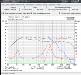
OK, well from the original, my comments are that the crossover point is too low (tweeter 3rd order distortion is very high at this frequency as per the HFC measurements; it would prefer somewhere like 2.5-2.8khz; also moving further away from its resonant frequency is good practice).
On the woofer section, the notch does not squash that big peak at 4.4khz; it needs to be hammered away; hence I went for a steeper slope; try plugging my values in at least to have a look. The woofer impedance also drops to 2ohms or so at 5k cause the breakup remains.
On the tweeter section, again the notch does not seem to be doing anything useful, and the weird impedance curve of this tweeter is dropping very low with higher frequencies. A CR is a better way to flatten the rising response around 10k and above.
What I tried to do was use a higher crossover point, steeper slopes, bash the woofer breakup, address the rising response of the tweeter.
It should be absolutely fine at 2kHz.
The 8 V drive level results in an SPL of 102dB, which is bloody loud and the low sensitivity of the system, about 80-82dB, is going to really make this limited by the woofers capabilities.
Still 8V at 2kHz is 101dB. With a 4th order acoustic slope at 2k you're looking at 6dB of attenuation at 2kHz if it's designed correctly. This is equivalent to the 4V distortion curve, putting the 3rd order at -53dB, lower than it is at 4kHz.
In a low sensitivity system, with max SPL limitations, I'd happily cross this at 2khz, unless the speaker was going to be abused or also possibly driven by clipping amplifiers.
I was just doing something not a million miles away from motokok's ideas.
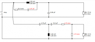
The standard tank notch proved useful on a 6" woofer around 5kHz. Usual 1:3 butterworth filter on the 8 ohm tweeter. This is not a design for you, just a demonstration of how the cheap and cheerful RC tank notch can cure breakup. But a proper LCR notch is better usually.
The standard tank notch proved useful on a 6" woofer around 5kHz. Usual 1:3 butterworth filter on the 8 ohm tweeter. This is not a design for you, just a demonstration of how the cheap and cheerful RC tank notch can cure breakup. But a proper LCR notch is better usually.
Attachments
With regards to baffle effects earlier on I was referring to them all really. In other words have you run both the tweeter and woofer traced responses through a tool that modifies them for the theoretical effects of your cabinet.
No I have not done that. I just put a baffle step circuit in and played with it till it looked reasonable to me. What tool does this?
I tried both motokok and system7's circuits. Motokok's for some reason the tweeter level was way down. By the time I adjusted it there were frequency response aberrations in the crossover region I couldn't iron out. Same with system7's. Although yes the slopes were significantly steeper and the woofer bump at 4.5k was no longer visible. I'll see if i can start from scratch and design with a tank notch or higher order slopes.
Last edited:
I created my own frd and zma files from the pdfs for the XO I knocked up, but have since deleted it  Summed response was flat as a pancake, honest.
Anyhoos, I may try to reconstruct it later.
The tweeter has a naturally sharper rolloff than a shallow slope; try 3rd order, try 4th order.
Summed response was flat as a pancake, honest.Anyhoos, I may try to reconstruct it later.
The tweeter has a naturally sharper rolloff than a shallow slope; try 3rd order, try 4th order.
- Home
- Loudspeakers
- Multi-Way
- Need help with crossover for Phenomax midwoofer and 3/4" Revelator