Hi, the sound of this nap 200 clone is ok but you hear distortion. Sound like crack even when you play soft.
The distortion is louder right the left.
If this is solve then I'm happy...
The using mpsa18 as first transistor.
Thx
The distortion is louder right the left.
If this is solve then I'm happy...
The using mpsa18 as first transistor.
Thx
That's possibly crossover distortion. It could be a bias setting problem or you could have a problem with the output transistors. The obvious question: Did the output transistors and drivers come in the kit or did you buy them separately?
If there is a difference in the sound from either channel, something is clearly different between them if the speakers swap over with same sound difference as previously. You should also be testing carefully for wrongly fitted transistors, badly solder joints and wrong value components like resistors, in the worst channel.
In the meantime, test the Vbe voltages of the output and driver transistors. That means to measure the Voltage between the base and emitter terminals of the transistors and it should be about 1 diode voltage drop or 0.6 -0.7V. It may not matter if you measure with either polarity, depending on whether the transistor is PNP or NPN and which probe you connect to either terminal.
In order for a Naim clone to work properly with correctly tracking bias current as the temperature slowly rises, the case should be closed and there should not be any holes to allow air to escape. In the genuine product, the case is the heatsink and this ensures the whole amplifier, including the 2N5089 sensor transistor (near the bias pot) warms up evenly. Mistakes there can be a disaster - be sure of what you are adjusting and how to do it properly.
Where possible, use IC clips or similar to connect to a powered amplifier or you will surely slip and cause shorts and damage with probes, whilst looking at the meter.
hi Ian,
i have receive the board including the power transistors on it.
to adjust the offset, see picture
http://www.diyaudio.com/forums/attachment.php?attachmentid=591539&stc=1&d=1484149576
i have receive the board including the power transistors on it.
to adjust the offset, see picture
http://www.diyaudio.com/forums/attachment.php?attachmentid=591539&stc=1&d=1484149576
Attachments
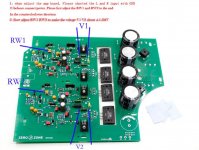
That is good and the procedure is correct for bias current setting but the instruction neglects to say that it will only work properly when the amplifier is in a sealed case. Why? because there are no heatsinks used with this Naim design, right? The sensor transistor is also a long way from the output stage and the heat of the output stage has to get there predictably by some means. That means is the bottom of the case and the air trapped inside. Don't try to set bias without the amplifier being in a suitably thick aluminium case with a heat spreader bar for mounting the transistors or your output stage will overheat and the bias setting will never be stable or correct.....to adjust the offset, see picture.....
That is my point, I hope you understand what is being said because that affects distortion and also whether the amplifier will remain stable (i.e. not burn due to thermal runaway) This is a quasi-complementary design and you may understand that you cannot simply position the sensor transistor on the heatsink as we do with complementary designs.
Now how about the the other questions, like checking the assembly again and testing the transistors?
Attachments

Last edited:
Ian,
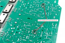
the sensor transistor is place on the back of the pcb.
i have place the 2SC2922 on heatsink. and it stay cool.http://www.diyaudio.com/forums/attachment.php?attachmentid=591544&stc=1&d=1484153209
the sensor transistor is place on the back of the pcb.
i have place the 2SC2922 on heatsink. and it stay cool.http://www.diyaudio.com/forums/attachment.php?attachmentid=591544&stc=1&d=1484153209
Attachments
When the amplifier is not producing much audio and there is only about 30 mA bias current according to a 5mV setting, of course the output transistors will be cool. They should only become hot when more power is produced and at even 50W continuous output power, they'll be very hot and you really need that spreader bar between the transistors and the case.
The pic I attached shows the outline of the heat spreader bar; a piece of thick aluminium about 180 x 28 x 6 mm, which is a neat fit in the large PCB slot in which the output transistors are located. You can also see the clamp bars used to press the transistors onto the spreader bar and the spreader bar to the case. These parts and the bolts etc are not supplied in the kits so you have to carefully make and assemble them yourself.
The schematic for each amplifier of the NAP200 is the same for all NAP models since 1972 but there is slight difference in the circuit of current source transistor TR3 as your comment about the MPSA18 transistors indicate. Do you have a schematic showing TR3a and can you post it?
Ian,
On this forum sombody post the diy nap 200 kit
With the bc239c and mpsa06 that drswing I have compare with the kit I have
In my kit they only use mpsa18 instead of the bc239c and mpsa06
If it's right I can change these 4 transistor and it must work
On this forum sombody post the diy nap 200 kit
With the bc239c and mpsa06 that drswing I have compare with the kit I have
In my kit they only use mpsa18 instead of the bc239c and mpsa06
If it's right I can change these 4 transistor and it must work
Ian,
Is there an other way to placelebrate the sensor the probe is that it's located on the back of the pcb is now bent to the pcb what is the best way.
Tomorrow I try to change the 4 mpsa18 for 2 x bc239c and mpsa 06 and see if this is solver my problems.
Thx
Is there an other way to placelebrate the sensor the probe is that it's located on the back of the pcb is now bent to the pcb what is the best way.
Tomorrow I try to change the 4 mpsa18 for 2 x bc239c and mpsa 06 and see if this is solver my problems.
Thx
The schematics you link are for the NAP140. The NAP 200 is quite different in some areas. TR3a is used in place of 2 x1N4148 diodes as a voltage reference for TR3 and the VI limiter circuits are more sophisticated. The attached schematic from #2177 was reverse-engineered and drawn by Algar_emi from the Caowei kit PCB. Your ZeroZone kit is similar but considerably cheaper, I believe and as a probable consequence, some of the unusual components may be fakes or at least non-genuine parts. That's easy to disguise when supplying finished, assembled boards like this and perhaps this is the general problem you have. In any case, why not check the voltages kindly posted by Algar_emi against your board, as a check for errors and incorrect operation? Obviously, supply voltages and currents will be different but you can calculate how different they should be by knowing the circuit component values and using basics like ohm's law.
BC239C transistors are obsolete so other On-Semi transistor types like 2N5089 have been substituted. I think any that you may buy now will be suspect as fakes if they are Motorola or Onsemi branded. I don't think 2N5089 will make the best substitutes, as other commonly available low-noise transistors might, but that is not for me to decide. The MPSA06 transistors are also obsolete On-Semi types but these are general purpose types and if you are going to replace them, BC546 or 546BB will do as well, provided Hfe is within the spec.
Note that TR7,7a,8,8a act as sophisticated current limiters for the output stage and errors in the assembly here can cause output distortion at high power. The amplifier must have some form of protection against shorts and careless handling of the speaker connections though, so it is unwise to simply remove the limiters, as many DIYs routinely do.
I doubt that the assembler would sell finished boards that didn't work at all, because the return claims would cost them more than the sales value. If you used them in any way different to the original design and recommendations though, any claims for just a badly working amp would not be valid. In particular, the case, the mounting of the output devices and power transformer ratings are always critical to the survival of these Naim amps. That's the first, obvious reason not to use high, incorrect power supply voltages and risk exceeding safe operating voltages and temperatures of the components.
This link is old but useful info. but some suggested replacements are no longer available either.
Transistor equivalents [Archive] - pink fish media
You don't need to access the transistor leads directly because the 27R and 2k resistors and C3 connect to it also, which will be easy to probe from the top. Just look at the PVB tracks and trace the circuit in that area.....Is there an other way to placelebrate the sensor the probe is that it's located on the back of the pcb...
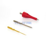
You may notice that new meter probes are sharp and don't slip on solder joints. This is often very helpful and a little sharpening of old probes on a fine stone or knife sharpener. is a good idea.
Attachments
Last edited:
I should have asked what you are calibrating at the legs of TR5 anyway. If you are trying to adjust bias current, you should be measuring 4.5-5mV voltage across either of the pair of large 0R22 resistors that are closest to the output transistors.
I buy the transistors at mouser or farnell these must be original not fake correct me if I'm wrong
I measure the hfe of each transistor and try to keep them the same. The best is to replace all transistors mpsa18 for BC546? and match the hFE ?
I measure the hfe of each transistor and try to keep them the same. The best is to replace all transistors mpsa18 for BC546? and match the hFE ?
Ian,
i have measure the following
BC546 hFE 220
MPSA18 hFE 696
MPSA06 hFE 162
BC239C hFE 490
what wil be the best possible option to use
thx man
i have measure the following
BC546 hFE 220
MPSA18 hFE 696
MPSA06 hFE 162
BC239C hFE 490
what wil be the best possible option to use
thx man
gent ebay h140 clone looking for some advice re input pair matching some post say shoud be the same and avondale say tr1 shoud be 10% more, i have got from mouser 100 divices bc546bta fairchid about 45 % hfe 286, 45% hfe 432 and 10% give strange reading and never the same so i tend to think bad bc546 or is this the norm
- Home
- Amplifiers
- Solid State
- NAP-140 Clone Amp Kit on eBay