Ordinary plastic insulation is good enough. Silicone and Teflon are not required.
Ordinary plastic comes in lots of varieties, most being a version of PVC.
EVERY connection between modules is a TWO WIRE connection.
The mains is a two wire connection plus the Protective Earth.
The transformer secondary to PSU is a two wire connection.
The PSU to amplifier is a two wire connection
The amplifier to speaker is a two wire connection
The RCA input socket to amplifier is a two wire connection.
All these TWO WIRE connections need both the Flow and Return wires to be close coupled for the whole route including the termination/s.
Preferable is to twist those close coupled wires.
Better again is to use screened twisted wire where the signal level is very low or the EMI is very high.
Coax is a two wire that is close coupled. But you must use both wires at both ends. Again the loop area at the termination/s must be minimised.
Last edited:
Ian.An overall principle of protective earth wired power supplies,..................
Naim NAP amplifiers were originally developed back in the 1970s and wiring schemes have improved somewhat since they were introduced...................
Good Naim clone board wiring is shown here in this thread a few times but you can still follow the connections using the better technique anyway. Here's a diagram showing how a up-market Naim Clone is wired.
That diagram (post2359) is seriously flawed.
See the enormous LOOP AREA in the speaker Flow and Returns !
Do Naim really wire up their speaker wires like that diagram?
The two 0V connections are incorrect. The Signal Return should connect to the Speaker Return wherever that meets up with the Power Ground.
Last edited:
As I may not have been clear enough on this, amplifier ground connections (that's OV or -ve in a single power rail design) are returned to power supply "star earth" which is then connected by a short heavy lead and terminal to chassis protective earth, along with the mains protective earth terminal but not compromising that secure connection. The design of star earthing schemes is an art in itself but it seems you bought a NAP 140 clone PSU board, so you'll have to follow that board - I've not used one other than in service work.
@ AndrewT. Not that I checked - That is NCC200, Avondale audio wiring as marked. Whilst it is good to upgrade earthing, if you want a clone, you need to consider cloned wiring too, as Naim continued for its own reissues, up to relatively recent years.
@ AndrewT. Not that I checked - That is NCC200, Avondale audio wiring as marked. Whilst it is good to upgrade earthing, if you want a clone, you need to consider cloned wiring too, as Naim continued for its own reissues, up to relatively recent years.
Last edited:
I have grounded my PSU to the chassis via of the ground pad on the PSU board that is the ground for everything else. This has removed 100% of my low-frequency hmmm. I am using a computer/PC soundcard as a preamp, I am still getting noise although just a small fraction of what I had before grounding power supply to the chassis, this is more of a low-volume high-mid frequency static type of a noise, This is a sometimes oscillating noise. Rrom here I will rewire and check for results, I have grounded the amp chassis to the computer chassis this seems to make no difference. I use this PC soundcard as a preamp for other amps and have no such noise issues with them. P/s This left over noise tends to vary from a constant static noise to a sometimes sounds like marching foot steps.
Last edited:
That seems like RF sensitivity from your description, which probably originates from your PC. You should be investigating the source of noise with what you have and I assume you have an MP3 player, a preamp of some sort in another amplifier etc. to provide an independent (ungrounded) signal. Then experiment and locate the source of the noise.
The obvious first test is to remove the signal source - just unplug it. Is it still noisy? Then short the input socket - still noisy? And so on.
The obvious first test is to remove the signal source - just unplug it. Is it still noisy? Then short the input socket - still noisy? And so on.
Ian Finch, You are correct the pc is the source of the noise.The preamp is provided by a aftermarket Asus soundcard.This distortion is negligible and outside of a simple ground issue I don't really want to mess with the computer. I did ground the chassis together and that seem to have no effect whatsoever, so I think it best to just live with it which is fine, in a different environment this may not be a this issue at all. Gratefully, Dave
Is it possible to use the NAP 200 clone as a monoblock bi-amp? One RCA input feeds into both the left and right connection on the board so both amplifier channels are fed the same information, it should be able to be used for bi-amping compatible speakers right?
Or is it not as simple as it seems?
Or is it not as simple as it seems?
Monobloc or dual mono construction is usually defined by separate grounding and power supplies. The NAP200 already comes close to dual mono, with separate supply windings but both are wound on the same transformer and the supplies remain at least AC coupled, to some degree.
If you must have dual mono, you may only need to source a pair of identical 28-0-28V or 28-0 +28-0V transformers. If you must have monobloc construction, buy a pair of NAP140 clone boards and build them as separate mono amplifiers because that's all "monobloc" means. Use the appropriate same components specified for the NAP200, if you want the amplifiers to sound any good, that is. The parts that come with NAP140 kits are a compromise of what's cheap, similar purpose and freely available - shame that the generic copied parts supplied, seldom result in good sound.
In my limited experience with them, I don't think there is benefit to Naim monoblocs. They are seldom even considered anywhere. I believe there is a benefit for conventional ultra low distortion audio amplifiers though, as high end systems demonstrate. The cost of high quality parts and construction that ensure that performance are really expensive though - since building esoteric quality amplifiers with generic parts will prove to be waste of time, if you really are stretching your hopes up to a $10,000+ audio system. Walk straight before you try to run with DIY 🙂
Would there be sonic improvements if I use one amplifier to power one speaker that accepts bi-amplification? meaning using the L speaker outs to the woofer speaker and R speaker outs to the tweeter by way of feeding one RCA in into both L and R inputs.
I was probably confused or uninformed about the usage of the term "monoblock" amplifier, from my understanding the term is used when the amplifier has dedicated similar/mirror image circuits for the left and right channel either within the same chassis or in separate chassis that produces more or double the power/wattage as compared to conventional amplifiers. I assumed it wasn't a monoblock or is far from one because both the negative speaker terminals has continuity that suggests they share a common ground.
I was probably confused or uninformed about the usage of the term "monoblock" amplifier, from my understanding the term is used when the amplifier has dedicated similar/mirror image circuits for the left and right channel either within the same chassis or in separate chassis that produces more or double the power/wattage as compared to conventional amplifiers. I assumed it wasn't a monoblock or is far from one because both the negative speaker terminals has continuity that suggests they share a common ground.
This is the way I experimented with bi-amplifying way back in the early 80s. I found that it was a big improvement. Each stereo amp had very short cables and located behind the speaker.Would there be sonic improvements if I use one amplifier to power one speaker that accepts bi-amplification? meaning using the L speaker outs to the woofer speaker and R speaker outs to the tweeter by way of feeding one RCA in into both L and R inputs.
Mono block means to me one amplifier in one chassis.I was probably confused or uninformed about the usage of the term "monoblock" amplifier, from my understanding the term is used when the amplifier has dedicated similar/mirror image circuits for the left and right channel either within the same chassis or in separate chassis that produces more or double the power/wattage as compared to conventional amplifiers. I assumed it wasn't a monoblock or is far from one because both the negative speaker terminals has continuity that suggests they share a common ground.
All other multichannel amplifiers cannot have as simple a Earthing/grounding arrangenment as a mono block and I beleive their performance is compromised as a result.
Dual mono does not match the simple Earthing.grounding of a pair of monoblocks.
Dual mono is two completely isolated amplifiers in one metallic enclosure.
I consider a 4secondary transformer feeding two channels of a dual mono as equivalent to using 4secondaries from two separate transformers feeding two channels of a dual mono.
Last edited:
Hi Ian, where i can see the Nap 200 schematic. The most popular Nap schematic on this thread is Nap140 and NCC200 clone I suppose. Thanks !Monobloc or dual mono construction is usually defined by separate grounding and power supplies. The NAP200 already comes close to dual mono, with separate supply windings but both are wound on the same transformer and the supplies remain at least AC coupled, to some degree.
If you must have dual mono, you may only need to source a pair of identical 28-0-28V or 28-0 +28-0V transformers. If you must have monobloc construction, buy a pair of NAP140 clone boards and build them as separate mono amplifiers because that's all "monobloc" means. Use the appropriate same components specified for the NAP200, if you want the amplifiers to sound any good, that is. The parts that come with NAP140 kits are a compromise of what's cheap, similar purpose and freely available - shame that the generic copied parts supplied, seldom result in good sound.
In my limited experience with them, I don't think there is benefit to Naim monoblocs. They are seldom even considered anywhere. I believe there is a benefit for conventional ultra low distortion audio amplifiers though, as high end systems demonstrate. The cost of high quality parts and construction that ensure that performance are really expensive though - since building esoteric quality amplifiers with generic parts will prove to be waste of time, if you really are stretching your hopes up to a $10,000+ audio system. Walk straight before you try to run with DIY 🙂
Adrian
Sent from my Nexus 5 using Tapatalk
Heh, heh - all NAP models share the same amplifier design 😀.
As discussed here before, the difference between models is in the power supply voltages (i.e. the output power) and a couple of resistors that control the bias currents in the first stages according to the different rail voltages. Newer transistors have been supplied with the kits and these should be matched according to the earlier discussion. If you look at the PCBs closely, you'll see the same circuit in the newer NAP 200 to even the original bridge-mode NAP250 model, which is the generic schematic seen everywhere on the web. It has the same 40V supply rails that the NAP200 has. The original NAP 140 is not what you get in the clone kits though. The supply voltage is lower at +/-34V for 70W/4R, both channels.
The NAP200 is a much improved PCB layout over the old 1970s designs and has quite a sophisticated and very good grounding layout for the power supply. It really does perform much better, as do the very good PCB copies from Caowei.
Consider that the NAP 200 is really about that PCB and using the correct parts and near dual mono wiring, not the older board design and generic parts that come in the cheaper kits. It's expensive to build but you can get all the difficult hardware including the special toroidal (500VA!) transformer from Fleabay or Aliexpress.
Actually, I have been a little terse in my reply and should have checked because there are a few small detail changes to the schematic for the NAP200. Algar_emi reverse-engineered a schematic from the PCB that seems credible - see post #2177 and follow the thread from there.
My Elac B5 speakers arrived today and the amp has been driving them for a good 2-4 hours now. What's weird is the amp still cold to the touch. Is this normal? I am expecting some warmth or at least room temperature, but the aluminium enclosure is cold just like when it started up.
Have you checked the bias currents of the drivers and outputs?My Elac B5 speakers arrived today and the amp has been driving them for a good 2-4 hours now. What's weird is the amp still cold to the touch. Is this normal? I am expecting some warmth or at least room temperature, but the aluminium enclosure is cold just like when it started up.
These are the biggest heat generators in your amplifier. The transformer comes next.
Have you checked the bias currents of the drivers and outputs?
These are the biggest heat generators in your amplifier. The transformer comes next.
To be honest, I don't know how to. The board was bought assembled and tested.
Naim amps do run relatively cool because they are a quasi-complementary design and operate with only about 30 mA bias current in the output stage.
The bias setting procedure has been detailed a few times in this thread. You probably don't have any schematic to refer to, so you need to identify the output transistors TR11 and 12 and the large "emitter" resistors, R11 and R12. Don't confuse them with the similar output resistor, R14. Measure the DC voltage across either R12 or R13. It will be very small and should be set to 7mV. If your meter is crap at lowest range measurements, measure across both resistors in series and adjust for twice the voltage at 14mV, which will be more precise.
Make any adjustments promptly after the amplifier has been closed and fully warmed up. If you are running the amplifier open, it will probably never warm up and stabilise, so don't try to set it without its case - you'll be wasting your time. Build your amp like the original, where the amplifier does eventually warm up warm after about 20 mins because the aluminium case is the heatsink.
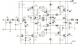
I don't know whose clone you have there and what, if any, part numbering is used. The reference numbers I've used here follow the attached schematic. Yours may have nothing, so you may have to deduce the part identities from the circuit and layout, which will likely be similar to the original anyway.
Also check out some more Naim set-up, history and other details on this site archive: Modifying Naim Audio power amplifiers
The bias setting procedure has been detailed a few times in this thread. You probably don't have any schematic to refer to, so you need to identify the output transistors TR11 and 12 and the large "emitter" resistors, R11 and R12. Don't confuse them with the similar output resistor, R14. Measure the DC voltage across either R12 or R13. It will be very small and should be set to 7mV. If your meter is crap at lowest range measurements, measure across both resistors in series and adjust for twice the voltage at 14mV, which will be more precise.
Make any adjustments promptly after the amplifier has been closed and fully warmed up. If you are running the amplifier open, it will probably never warm up and stabilise, so don't try to set it without its case - you'll be wasting your time. Build your amp like the original, where the amplifier does eventually warm up warm after about 20 mins because the aluminium case is the heatsink.
I don't know whose clone you have there and what, if any, part numbering is used. The reference numbers I've used here follow the attached schematic. Yours may have nothing, so you may have to deduce the part identities from the circuit and layout, which will likely be similar to the original anyway.
Also check out some more Naim set-up, history and other details on this site archive: Modifying Naim Audio power amplifiers
Attachments
I will try to probe the terminals later. Could it also be because I'm using a 300VA transformer instead of the original 430VA?
No, the 430 VA rating is more than sufficient for the task and even a 300VA transformer could be considered overkill. The over-sizing is not needed to maintain the tiny bias currents which are regulated by the circuit anyway. The over-size transformer is about better sound quality and is specific to the brand and construction qualities of the transformer originally used.
I should point out that the schematic is a general NAP schematic, suiting almost all NAP models since the 1970s. The transistors and other parts used will be different to the originals because those are obsolete. Only TR4 and TR6 are original.
I should point out that the schematic is a general NAP schematic, suiting almost all NAP models since the 1970s. The transistors and other parts used will be different to the originals because those are obsolete. Only TR4 and TR6 are original.
- Home
- Amplifiers
- Solid State
- NAP-140 Clone Amp Kit on eBay