Andrew thay are working well the off set for 80% is in the range 25>30mv however the rest are 40>50 mv note last rebuild i did not match tr1 tr2 , so first move match tr1 tr2 and then look at the the offset once more, comments please
David
David
I haven't chimed in for a while.
I bought the following assembled board from eBay.
2016 Assembled Black Box ?Clone Naim NAP200 Amplifier board DIY amp 75W+75W L
I received no schematics or anything so I don't know whether the parts are up to specifications. But assembly went on well and it runs well now.
I've mentioned earlier in page 238, the amp runs cool with an Elac B5.
From Spotify alone via ChromeCast Audio optical out to my Matrix Mini-I DAC, I think I am a little bugged by how my setup sounds. The imaging is quite smeared and more of a 3-blob soundstage (left channel, center channel, right channel). Singers instead of sounding like they're singing from a single point is imaged like they're from a general area in the middle channel. From impressions by people who has the Elac B5, they mentioned the highs could be recessed and the speakers do sound dark to me.
Jazz however sounds nice, especially anything winded like trumpets, sax, or trombone. The same imaging problem applies to jazz. Modern pop songs with lots of electronic elements and no soundstage sounds nice.
I think the sound from my turntable could be better, but I'm not sure. I haven't done any critical listening up until last night, though I have been bugged about this imaging issue for a while.
How is your NAP200/140 clones working out for you guys? And could the reason be because of my setup instead and not just the amp?
Chromecast Audio > Optical to Matrix Mini-I DAC > Lehmann Black Cube Clone (pre) > NAP200 Clone > Elac B5
Computer > USB to Matrix Mini-I > pre > power > speakers
Telefunken S500 > TCC-TC750 > pre > power > speakers
Playstation > pre > power > speakers
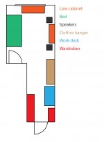
Attached is my small room diagram. My speaker stands are cheap reclaimed wood, probably from those wood pallets. I got them from a friend.
They have no spikes, but has plastic nubs that you nail at the foot of chairs or tables to protect the floor. Between the stands and speakers I've placed felt pads because the platform is uneven.
I've also tried to change the positioning with the speakers at the top of the room but the imaging was worse.
By contrast, if I use my Sennheiser HD525 headphones and plug them into the Lehmann Clone which is both a pre and headphone amp, imaging is precise and taut.
I bought the following assembled board from eBay.
2016 Assembled Black Box ?Clone Naim NAP200 Amplifier board DIY amp 75W+75W L
I received no schematics or anything so I don't know whether the parts are up to specifications. But assembly went on well and it runs well now.
I've mentioned earlier in page 238, the amp runs cool with an Elac B5.
From Spotify alone via ChromeCast Audio optical out to my Matrix Mini-I DAC, I think I am a little bugged by how my setup sounds. The imaging is quite smeared and more of a 3-blob soundstage (left channel, center channel, right channel). Singers instead of sounding like they're singing from a single point is imaged like they're from a general area in the middle channel. From impressions by people who has the Elac B5, they mentioned the highs could be recessed and the speakers do sound dark to me.
Jazz however sounds nice, especially anything winded like trumpets, sax, or trombone. The same imaging problem applies to jazz. Modern pop songs with lots of electronic elements and no soundstage sounds nice.
I think the sound from my turntable could be better, but I'm not sure. I haven't done any critical listening up until last night, though I have been bugged about this imaging issue for a while.
How is your NAP200/140 clones working out for you guys? And could the reason be because of my setup instead and not just the amp?
Chromecast Audio > Optical to Matrix Mini-I DAC > Lehmann Black Cube Clone (pre) > NAP200 Clone > Elac B5
Computer > USB to Matrix Mini-I > pre > power > speakers
Telefunken S500 > TCC-TC750 > pre > power > speakers
Playstation > pre > power > speakers
Attached is my small room diagram. My speaker stands are cheap reclaimed wood, probably from those wood pallets. I got them from a friend.
They have no spikes, but has plastic nubs that you nail at the foot of chairs or tables to protect the floor. Between the stands and speakers I've placed felt pads because the platform is uneven.
I've also tried to change the positioning with the speakers at the top of the room but the imaging was worse.
By contrast, if I use my Sennheiser HD525 headphones and plug them into the Lehmann Clone which is both a pre and headphone amp, imaging is precise and taut.
Attachments
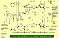
As Ruwe mentioned, I don't understand what your voltage reference point is for your measurements because they seem wrong or irrelevant to what you need to know about TR4,5,6.......Tried to deal with dc out increase without success, the other channel is working perfectly and made some measurements......Also i attached a schematic with voltages wich seems different to the working channel. In red between brakets are the voltages from "defective" channel.
I can adjust bias and is stable.....
An externally hosted image should be here but it was not working when we last tested it.free picture hosting
There are a few voltage measurements in-circuit that indicate correct operation so when troubleshooting semis, start with direct measurements of voltage across Base and Emitter (Vbe) because you know that whether PNP or NPN, a working bipolar transistor in a linear circuit has to be forward biased by a "diode drop" of about 0.65V. Then measure the C-E voltage or Vce to check they aren't shorted. This voltage (Vce) could be anywhere depending on the circuit so they may need to be removed to check an ambiguous low reading. Again, measure directly, not with respect to ground, the rails or anything in the other channel.
An important issue with clones and using schematics that were intended for other products is that we confuse them and the extra details and directions on Avondale schematics that won't always apply. Another is the constantly changing substitutes and their different pinouts that may suit the PCB supplied but then the parts on the original schematic won't. You may think that because you have a 2N5551 marked part that it is genuine but it may be a re-marked generic type with japanese ECB pinout instead of US EBC pinout. Original MPS series semis may be copied with correct (reversed) CBE pinout but I have seen copies which were CBE, EBC and ECB.
You could call them fakes but often they prove to be adequate in the applications and I guess that's why people keep buying the cheap kits - because they usually work OK in conservative use. Often, PCBs like LJM's will match the semis supplied, such as 2SD667/B647 supplied instead of ZTX653/753 but don't confuse the PCB connections when you start tinkering with other unchecked cheapo Ebay components.
I've said several times that those substitutes for the VAS transistors are completely wrong from a sound quality point of view and will guarantee you won't hear Naim sound. I can't see why anyone would build the kits unless looking to recreate it but I guess most constructors wouldn't know or don't care much - just want something simple that is associated with a respectable brand

Yes, i am agreeing on this 100%, Huge sound difference comes from VAS transistors.VAS transistors are completely wrong from a sound quality point of view
ZTX series = hell of a drive power + soft highs.
Toshiba 2SA1145 series = alot less drive, highs different, BUT EASIER to listen in long term, Reggea, melody for example
Unless your amplifier power supply is poorly arranged with maybe a single winding transformer instead of dual windings or 2 separate transformers for correct dual mono operation, I doubt your amplifier will have anything to do with poor stereo imaging. You will need to drive the headphones from the amplifier output to verify this. That won't be simple but Google will always find something like this has been done already, just search it......From Spotify alone via ChromeCast Audio optical out to my Matrix Mini-I DAC, I think I am a little bugged by how my setup sounds. The imaging is quite smeared and more of a 3-blob soundstage (left channel, center channel, right channel). Singers instead of sounding like they're singing from a single point is imaged like they're from a general area in the middle channel. From impressions by people who has the Elac B5, they mentioned the highs could be recessed and the speakers do sound dark to me.
Jazz however sounds nice, especially anything winded like trumpets, sax, or trombone. The same imaging problem applies to jazz. Modern pop songs with lots of electronic elements and no soundstage sounds nice.
I think the sound from my turntable could be better, but I'm not sure. I haven't done any critical listening up until last night, though I have been bugged about this imaging issue for a while....
Don't forget that with a centre channel, you no longer have a stereo system but the source will be stereo and a DSP(?) will be generating the sound "image" Look there for clues, at the settings first and even something as simple as speaker connection phase.
Unless your amplifier power supply is poorly arranged with maybe a single winding transformer instead of dual windings or 2 separate transformers for correct dual mono operation, I doubt your amplifier will have anything to do with poor stereo imaging. You will need to drive the headphones from the amplifier output to verify this. That won't be simple but Google will always find something like this has been done already, just search it.
Don't forget that with a centre channel, you no longer have a stereo system but the source will be stereo and a DSP(?) will be generating the sound "image" Look there for clues, at the settings first and even something as simple as speaker connection phase.
Thank you very much Ian, your replies are always informative.
I'm sorry I didn't mean to confuse. My setup is stereo with no center channel. When I mention 3 blob soundstage I meant the stereo setup sounds like its coming from 3 sections which is left, center, and right. I have no center speaker.
I was planning to make a speaker out to headphone adapter like the Hifiman HE-adapter, or Grado adapter. It won't take too long. I already got the 4 pin xlr cable from a previous project.
the difference between the base voltages is the first effect that affects output offset. If you have 10mVdc across the bases and a DC gain of 1 then you have 10mVdc of output offset plus a tiny bit that has been divided by the gain.Andrew thay are working well the off set for 80% is in the range 25>30mv however the rest are 40>50 mv note last rebuild i did not match tr1 tr2 , so first move match tr1 tr2 and then look at the the offset once more, comments please
David
The next effect is that due to the different Vbe of the input transistors. If you have a pair that are at the same operating current and have a difference in Vbe of 2mVdc, then these transistors will give an extra output offset of 2mV.
The two effects of base voltage and Vbe add together and one could be -ve with respect to the other.
Back to the base voltage diff.
This is V at base = base current * effective resistance to reference.
When you have two identical transistors operating at the same temperatures and the same currents and the same voltages then a difference in base current will be ZERO.
Now combine that with identical base resistances to Vref and you have ZERO output offset. And as long as you can hold the Tj to match inside the two transistors the output offset will not drift.
Your input resistor may be creating the offsets you have measured.
Try shorting the 27k with a high value resistor (when completely OFF and discharged) 27k||220k = 24k
Measure the +ve or -ve offset before and after, when the amp is cold and after fully warming up. That gives you some information on which to base the next adjustment.
Last edited:
In your schematic the capacitors nearest the LTP are the wrong way around. Normally, the LTP bases will be negative wrt ground.My build is identical with schematic but i use MJE243/253 drivers and NJL0281power transistors
An externally hosted image should be here but it was not working when we last tested it.free picture hosting
(PS: this is not a correct Naim schematic BTW)
Andrew thank you i now have abetter understanding of the ltp over the next week or two i will have a play
Mr Vereker did do many things his own sweet way. I imagine Les Wolstenhome at Avondale Audio would just follow the hallmark design unless there was a compelling reason not to.In your schematic the capacitors nearest the LTP are the wrong way around. Normally, the LTP bases will be negative wrt ground.
(PS: this is not a correct Naim schematic BTW)
Attachments
A Naim is very difficult to reverse engineer so many give up and try to make their own "improvements" and end up with an underperforming Franken-Naim.Mr Vereker did do many things his own sweet way. I imagine Les Wolstenhome at Avondale Audio would just follow the hallmark design unless there was a compelling reason not to.
The schematic on the right does not accurately depict a Naim (assuming that's what it is meant to be for) and both have a basic mistake in them. Best not to build from them verbatim.
That's a clever way to avoid copying!!
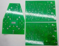
I take it the pcb is carefully disguised as well; black substrate, and black overlay?
HD
I take it the pcb is carefully disguised as well; black substrate, and black overlay?
HD
I attempted to reposition my speakers and see whether there's better imaging I can get from my setup and I'm happy that I managed to.
It turns out its because of a combination of a few things, mainly the distance apart and from the back wall.
They're now about 5'6" apart and 2' from the back wall. The roughly 3' shelf has been moved to simulate a faux wall so the listening area is only 11.5'x9.5' and doesn't include the 2nd portion of the room.
I achieved better imaging from my turntable too instead of my Spotify. Though I'm a bit miffed that my speakers are so revealing that I'd have to clean the stylus sometimes halfway through a side. Gunk is barely visible but vocals distort noticeably.
Speakers are also toed in but towards my back wall as suggested by someone from avsforum.
One question, since the NAP200 was designed to be left turned on, how much different is the sound quality between freshly turned on and left on for a few hours/days?
I'm asking because I don't have the luxury to leave it on, I simply don't trust my roommates if anything happens to it.
I don't believe it's necessary or safe to do that, really. It is an extreme solution to an historic, unresolved design problem with slow warm-up. 'Just another part of the spin and flat-earth philosophy accepted as fact by Naim enthusiasts......since the NAP200 was designed to be left turned on, how much different is the sound quality between freshly turned on and left on for a few hours/days?....
More importantly, you have an unspecified clone with components in an assembly that may or may not be safe to leave powered on unattended. Your build will almost certainly be different to the original design and other clones alike. It won't perform the same as the original product either. Who's even to say it will not sound better to you when it's cold rather than warm?
Naim factory products may be built to withstand being powered up 24/7 but their problem is a slow (20-30 min.) warm-up, with the case being the heatsink and the air inside as part of the thermal coupling to the control element, TR5. That could mean 30mins before idling bias is in a sweet spot of around 30 mA but funny enough, most people who have evaluated various bias settings and posted in audio forums seem to agree that it's far from critical. The NAP 200 is a little quicker than some older models (in my limited experience) probably because the TR5 transistors are mounted on the copper side, close to the case bottom plate.
Since this is only a matter of subjective sound quality, don't worry about a matter you don't seem to have experienced yet. If you come to believe the sound is unpleasant when cold, then use common sense and do something else for the minutes it takes to warm up. To some degree this will apply with all audio systems and there is also a psycho-acoustic effect of your own ears becoming accustomed or adjusting their sensitivity to liked or disliked sound qualities.
Don't let seeds of doubt rule your own perception though - make your own assessments and be happy that you have something that may not be identical to a Naim product but possibly cost you less than 10% of one 🙂
Last edited:
Member
Joined 2009
Paid Member
That could mean 30mins before idling bias is in a sweet spot of around 30 mA but funny enough, most people who have evaluated various bias settings and posted in audio forums seem to agree that it's far from critical.
In fact, there are measurements of distortion vs bias that have been published on the internet here: Naim, NAPs, Naits, distortion and bias-current settings
These measurements suggest a lot of tolerance, with the range 20mA to 40mA being perfectly fine.
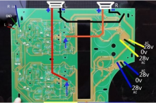
Haha...absolutely not - easy enough for anyone with a screwdriver to see and even scan the pattern without disassembly.....I take it the pcb is carefully disguised as well; black substrate, and black overlay?.....
The Caowei board for the NAP 200 referred to is an exact copy, right down to the adjustable 2-axis mounting slots, finely slit grounding pads and traces. It's a work of art, just like the original. The 2nd attached pic. is another manufacturer's NAP140 boards which accept either MT200 or T03 o/p semis.
Unless we feel the brand of FR4 makes a difference, Caowei's clone boards are virtually the equal of the original boards. The real differences of builds are only in the component and PSU options (many of which can't be reliably obtained or replicated any more), the use of wiring looms, connectors and of course, the size and construction of the case and heat spreader.
No, these aren't like the majority of cheap kit PCB boards you find and if Naim screwed up the design of the PCB, so have the clone suppliers. Screwing up the star grounding (as happened on a couple of models) is a wiring issue.
Attachments
gents looking number article naim JV, thay have spent months getting the enclosure right so what chance do we have, all sorts come in to play material paint etc all come in to play, and the question begs QA QC of the parts we use.
note i do not leave my system on at all however it is on all day and has been so 6 years now the only issue ever 22000uf cap started leaking ebay what can i say
note i do not leave my system on at all however it is on all day and has been so 6 years now the only issue ever 22000uf cap started leaking ebay what can i say
Hello!
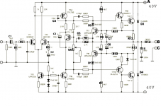
Sch Naim
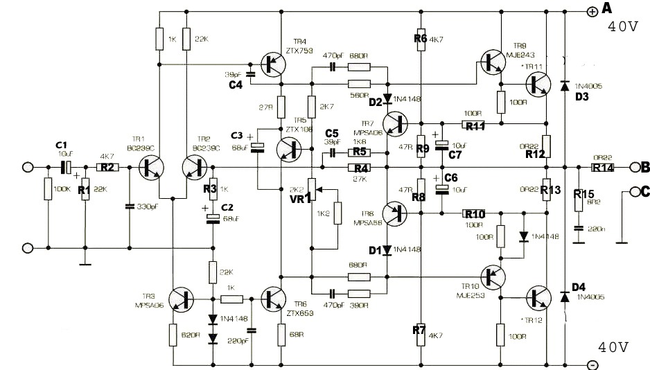
What is the heating temperature of the transistors Tr4 ZTX753, Tr6 ZTX653?
The transistors Tr4, Tr6 heat up to 60 degrees! Is this normal?
Sch Naim
What is the heating temperature of the transistors Tr4 ZTX753, Tr6 ZTX653?
The transistors Tr4, Tr6 heat up to 60 degrees! Is this normal?
These two transistors pass ~10mA.
With 40V supply rails they will dissipate ~400mW.
Check how much they need to be derated when operating at this power.
You can check this current by measuring Vdrop across 68R & ~27R
With 40V supply rails they will dissipate ~400mW.
Check how much they need to be derated when operating at this power.
You can check this current by measuring Vdrop across 68R & ~27R
Thank You.These two transistors pass ~10mA.
With 40V supply rails they will dissipate ~400mW.
Check how much they need to be derated when operating at this power.
You can check this current by measuring Vdrop across 68R & ~27R
Pk = 40V*7,5mA = 300mW, Ik_tr4 = 7,5mA.
Is the original Naim the same current?
- Home
- Amplifiers
- Solid State
- NAP-140 Clone Amp Kit on eBay