how can I install 4 transistors (BC550Cs) into same holes designed for a single transistor? It is a practical question, I can probably fit two of them but not sure about 4.
thx
al
thx
al
solder them together as hard wired, leaving just 3 legs reaqdy to be inserted into the pads.
I have done cascode of a single, but that is just two transistors into 3pads.
I have done cascode of a single, but that is just two transistors into 3pads.
If you do, just use 4 BC550C.
Nigel, did you mean 2 transistors for each half of an LTP, making 4 in total per LTP? Or 4 per half, making 8 in total?
NAP-140 Toroidal power supply- Ebay kit
1. Would these Torods be suitable for powering the Chinese Naim 140 clone kits found on Ebay?
2. If so which would be preferred the 500va or 330va?
3. I am assuming these are a dual secondary source 25 Volt X 2 to power the supplys for both channels from the single Torod?
If my assumptions are incorrect please put me on the correct path and recommend a transformer setup suitable for the Naim 140 2 channel amp.
Thank you.
Avel Y236801 500VA 25V+25V Toroidal Transformer - Parts Express
Avel Y236750 330VA 25V+25V Toroidal Transformer
It seems that the original Naim design requires two 28x2 secondaries, or two 28-0-28 secondaries. I think a single dual secondary (e.g., 28x2 or 2X28 CT) might be used to supply both channels so I would chose 500VA version with 25x2 secondaries. But please wait for experts response to be on the safe side.
NAP140:
The 140 indicates the total power into a 4r0 test load.#
That tells you that the 8ohms rated amplifier has a total maximum output of around 80W i.e. approximately 40W+40W into 8+8ohms
A suitable transformer for this would be 0-25, 0-25Vac, or 25-0-25Vac, @ 80VA to 160VA.
I would choose the 160VA as that is my lower limit for power amplifiers, 200VA, or 250VA, would be suitable.
Suggesting 500VA for a 40W ClassAB amplifier seems daft.
The nap140 clone will work with much higher VA rated transformers.
But be wary of higher voltage.
Last edited:
Nigel, did you mean 2 transistors for each half of an LTP, making 4 in total per LTP? Or 4 per half, making 8 in total?
After matching pairs ( good enough as Naim has unmatched LTP sides ) add the extra transistors under the PCB. Use some glue to keep it firm. Wax would work. That's 8 total per stereo amp. Gains like 408 and 415 are pairs in my book. Don't hold the transistors and allow a >1 minute test. Make sure your meter battery is OK. Do an end of run test to be sure the measurements remain the same. Often the gains are so similar as to make Vbe the better test. A glass bowl over the tested device would be a simple temperature precaution, air currents are bad news when testing.
I used a test jig that mimics an LTP.
Emitter resistors can be 0r0
Collector resistors can be 1k0+-0.05%
Base resistors can be 0r0, when testing for collector current match, and testing Vbe,
or 1k0 +-0.1% when testing for Ib to calculate the hFE
Collector resistors go to 10Vdc.
Emitters coupled together go to 0Vdc
Bases coupled together (except for hFE) go to a variable voltage varying from 0.3Vdc to 1Vdc. A 2k pot wired in series with a 10k resistor does for this. 10k to 10Vdc and bottom of pot to 0Vdc.
Clamp the two transistors face to face for a bit of Thermal Coupling. The clamp also provides a bit of shielding from draughts. Yes, leaving a door open, or walking across the room will change the results.
Measure the Vdiff at the collectors tells the builder how different the "matched" transistors are.
As one slides the base voltage up, one can monitor the Vdiff collectors and see how well the two transistors track each other.
If Vdiff acros the collectors is 0.0mVdc, then the Vdrop on each collector load is identical and the Vce of each transistor is identical.
This results in identical Ic and identical Pq giving matching Tj. Matching of Tj is critical to getting transistor matching to work for you.
Waiting for 1minute, nor for 1hour does anying about getting Tj for each DUT to match.
This is the same set up I used to match the tracking of the LSK170 jFETs that I offered for sale.
grades A & C are still available in swap meet.
BTW,
LSK170 make a good swap for BC550c in the input LTP of many power amplifiers. Worth experimenting, Especially of one adds a BF244c as a cascode.
Last edited:
Naim seemed to sell big transformers as their main upgrade path. The capacitors were smaller in value than many American designs. When the Nait came out a reviewer said Naim were bad people to fit cheap capacitors. Naim supplied what the reviewer thought more in keeping with other designs. The " better " amplifier sounded worse. If forced to use a smaller transformer buy 4700uF with good ripple ratings. Try 2 sets. If the latter sounds boomy you will be in the Naim way of thinking. Some Japanese amps circa 1975 used 2 x 2200 uF, they sounded very good. Many will use 250VA and 2 x 22 000 uF. I suspect that would be a long way from how Julian Vereker saw things.
To be clear I do not automatically agree with how Naim saw things. I just give simple ideas to follow in the spirit of the original.
One idea which I rather liked is that the amplifer is a pendulum that works between the house mains supply and the speakers. The amplifer is in some ways just a gear box. This idea was tested and found to be true ( Hi FI Choice ? ) . It also showed that class AB most likely could sound better than class A ( in transistor I think I agree ). If the class AB distortion is held down low enough the ear will take it to be as good as class A. The mains transformer working as a choke to store energy which it can't in true if class A. The latter was proven to be true. From this the Naim conjecture of dedicated mains supplies sounding better was proven to be correct. These days mains noise is thought the important factor. In reality the resistance of the mains wire is prime. Class D makes this doubly so. The slightly bass light sound of class D might be down to this alone. I found using a monobloc construction can make it worse! I sold the solution to that so best I don't say more.
Some class A amps are over biased AB. That really is a nice idea. If lets say 5 watts class A any load and 50 watts AB 4R that is a very nice amplifier. It was shown nearly everyone listens at 5 watts regardless. The larger houses allow larger speakers of better efficiency ( 82 dB/watt low, 105 dB/watt high ). Above 5 watts the major distortion is ourselves. This would be the only reason to doubt the Naim amps. They would need to be converted to the more modern NPN/PNP output stage to consider that possibility I feel. Personally I wouldn't do it. The tantallum capacitors would be my doubt. The cheap Panasonic FC should be better. Use the higher voltage ones when you can.
As as side issue about noise. Douglas Self showed many years ago that the dynamic range of pick ups is a myth. That by hiss alone a shure M44-7 beats all. Many years later by pure chance I proved him right. A M44-7 in a SME 5 used for 78 transcription ( 0.7 for LP ) sounded better than most other things I ever heard and certainly better than the V15/4.
Self showed that with care an MC might be made as good. The reason most people never heard this is the Shure is a chalenge to most preamps. My Lyra is better if enough care taken. The SME 5 is not my favourite. It seems to be ideal with the 44-7. Much like an easy to live with Decca London ( the LP killer ). Stereo is not it best measured quality, fine in reality.
Having spent years perfecting MC stages a friend thought I would be very receptive to why power amps need low noise.
My best ever pick up compromise is the Denon DL 110. If you heard one sound bland it is the preamp alone. They are magical devices that seem happy in most turntables. You will need about 1 mV senstivity. A gain of 250 seems about right. 15 and 17 gives about that. The latter 3180/318 uS. Take the 15 up if you need to. Is the Denon as good as my Lyra Helikon? It's close. The AT95 is also very good.
I'm starting to run out of T3.15A fuses... 🙂
I'll build something similar to your lamp-in-series solution, Nigel, in the short term (I've been using a series bulb for testing purposes anyway), but I've just ordered one of the following that I'm expecting will be a permanent solution that will also protect against the occasion when the mains is restored following a power failure:
220V 1000W Transformer Delay Power Soft Start Protection Board for Amplifier AMP | eBay
Chris
The soft-start board arrived today from China in a record time of 7 days, I was expecting to wait about 7 weeks.
Although the board works as expected there's just a niggling doubt that at some point the dropper capacitors will fail (or gradually drop in value over time as I have seen elsewhere) and either de-energise the relay - placing the 5W resistors (of undeterminable manufacturer) under a permanent large load, or whack 230V AC across the low voltage part of the circuit. I can't think of a good outcome for either of these scenarios.
I'm going to therefore follow the good advice of others and substitute in a small transformer to isolate the circuit from the mains supply. I think the board can accommodate this with a few tweaks by removing/shortening a few of the high voltage tracks, drilling a few small holes and then point-to-point wiring the transformer input and output pins. A small amount of hot-melt glue may also be required to hold down the transformer.
Some replacement 5W resistors have been ordered from a trusted supplier, as well as some new electrolytics, diodes and a Panasonic relay - the Omron part supplied looks suspiciously fake.
There were also a couple of 3W resistors in series with the low voltage path, these were getting far too hot for my liking, and so this modification also allows these to be removed.
Hopefully all of this will make the thing more reliable in the long term and the components will be a known quantity.
Granted a lot of parts will be replaced, but the actual PCB was easily worth what was paid for the entire built unit.
Consider the possible adoption of a current saving arrangement for the relay/s
I usually use 15V or 18V from a 3 pin regulator as the supply to a 12V relay. (30V for 24V relay/s)
Then the relay is fed through a dropping resistor of similar value.
An electrolytic provides the 15/18V pulse to trigger the relay.
After the cpacitopr pulse has dissipated it runs at about half rated voltage and half rated current and about quarter of rated power. The resistor dissipates similar power so total power consumption is roughly halved. Everything runs cooler.
I have used both hot melt glue (quick) and clear window sealer (slow).
I much prefer the clear sealer. It is strong and flexible and cheap.
Noise.
Vn(RMS)= sqrt/(4xkBxTxRx{F2-F1}) noise.
KB is Boltzmann constant. kB = 1.38 x10 ^(-23) ( 10 power minus 23 )
T is temperature in Kelvin ( 273 + C if 30 C = 303 K is a good approximation ) We might get 30 C if music not too loud.
R is the resistance of the device
( Delta F, F2 -F1 could be 20 000 - 20 as typical hi fi bandwidth 20 000 is good enough ). It may be wrong, but should give correct relative results.
All the above to a good approximation.
I estimate with luck 4 x BC550C would be 200 nV ( a sensible guess ).
4K7 NAP input resistor 1.25 uV
1K feedback resistor 0.6 uV
Noise related to 1 watt at gain of 28
4 x BC550C -114dB
4K7 -98 dB
1K -105dB
Taken simplistically as 6K total = 1.4 uV = - 97 dB
That seems a good result
Now lets look at 3 x 200 R which is a realistic result of noise optimisation.
600 R = 450 nV = - 107 dB
There will be other noise sources which are harder to change. Also it is not correct to assume the noise is simple addition of resistors. As the error is the same each time it gives some idea how it is changing. If the compensation networks are retained this limits the scope of the improvement to about 1K4 @ 700 nV and -103.2dB
Lets see what happens if we raise the gain to about double using 500 R ( 900R total ). 900R = 550 nV. At gain of 55 Circa -100 dB. That means we have doubled the gain of the power amp and still have a small noise reduction over standard. This also means a passive preamp will not introduce too much noise compared with a standard NAP. A gain of 55 should allow a CD player to drive the NAP directly. Slightly higher gain I suspect will sound better. Double gain is usually OK. Never reduce the gain without test gear.
It. I would prefer 1K and 1n5 as a cautious R2 for Tr1 input. My suspicion is we still will beat the standard amp and the noise spectrum will be white rather than blue and have a gain jump.
Agreed - with a comment that glues for mounting transformers should be non-softening so that if the transformer does run hot for any reason, that the glue can't melt again, resulting in a loose mains connected disaster, rolling around inside the amplifier. There are thermoset hot melt glues that have more realistic (>100°C) temp. ratings, but not in common stick form. I suggest "don't do it" anyway......I much prefer the clear sealer. It is strong and flexible and cheap.
I received the BC239C for the LTP today, and after testing they seems genuine. Installed a matched pair (higher HFE for TR1) and the amp is working perfectly. Here the volts readings I got.
Gain: with 50mv input, got 1.4Vac output, or 28.9dB
BW (ref 1Khz) = 51Khz
With TR1-TR2 with the same HFE, I got 0.6V output dc offset, with TR1 (500) and TR2 (430) I have around 10mv 😉
I'll be able to provide matched BC239C pair for their Naim clone if anyone interested. I'll start a thread in the Swap Meet section shortly...
According to Chris the BC239C is the original part Naim uses...
Attachments
Last edited:
I am interested in a pair. How can I pay you? I have the same Nap200 board (single unit).I received the BC239C for the LTP today, and after testing they seems genuine. Installed a matched pair (higher HFE for TR1) and the amp is working perfectly. Here the volts readings I got.
Gain: with 50mv input, got 1.4Vac output, or 28.9dB
BW (ref 1Khz) = 51Khz
With TR1-TR2 with the same HFE, I got 0.6V output dc offset, with TR1 (500) and TR2 (430) I have around 10mv 😉
I'll be able to provide matched BC239C pair for their Naim clone if anyone interested. I'll start a thread in the Swap Meet section shortly...
According to Chris the BC239C is the original part Naim used...
al
The currents marked in red don't add up !I received the BC239C for the LTP today, and after testing they seems genuine. Installed a matched pair (higher HFE for TR1) and the amp is working perfectly. Here the volts readings I got.
Gain: with 50mv input, got 1.4Vac output, or 28.9dB
BW (ref 1Khz) = 51Khz
With TR1-TR2 with the same HFE, I got 0.6V output dc offset, with TR1 (500) and TR2 (430) I have around 10mv 😉
I'll be able to provide matched BC239C pair for their Naim clone if anyone interested. I'll start a thread in the Swap Meet section shortly...
According to Chris the BC239C is the original part Naim uses...
395mV across 270r is ~1.46mA, not the 1.85mA shown, (or is that 39.5V, giving a Vdrop of 500mV?)
1.85 +1.7 (plus a bit of base current) adds up to 3.65mA, not the 4mA shown.
4mA across a pair of 330r drops 660mV. That is probably very close to the correct value (40V-39.4V is shown).
Starting from the 4mA one would expect the 1.7mA to be around 2.5mA indicating ~ 26V at the collector.
Note also the 85mV and 8mV of mismatched Vbe at the -IN & +IN inputs. This difference would match with the 1.85mA:2.5mA mismatch of the inputs.
Last edited:
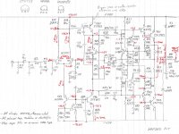
The currents marked in red don't add up !
395mV across 270r is ~1.46mA, not the 1.85mA shown, (or is that 39.5V, giving a Vdrop of 500mV?)
1.85 +1.7 (plus a bit of base current) adds up to 3.65mA, not the 4mA shown.
4mA across a pair of 330r drops 660mV. That is probably very close to the correct value (40V-39.4V is shown).
Starting from the 4mA one would expect the 1.7mA to be around 2.5mA indicating ~ 26V at the collector.
Note also the 85mV and 8mV of mismatched Vbe at the -IN & +IN inputs. This difference would match with the 1.85mA:2.5mA mismatch of the inputs.
I believe it says 39.5V not 395mV.
Therefore there is 0.5V across the 270R resisitor = 1.85mA
Nice to see Algar get the same ZTX VBE as I got i.e. 0.5V. Took ages before anyone would believe this figure!!
- Home
- Amplifiers
- Solid State
- NAP-140 Clone Amp Kit on eBay