I am surprised this has solved your hum problem. I would not expect a lack of quiescent current (in one channel) to cause 50Hz hum (in both channels).
I was surprised as well, but the hum vanished following the part swap and it was also possible to make it stop prior to replacement by applying downward pressure to the trimmer. Not sure if you saw a comment in an earlier post whereby the hum could be made to go away by knocking the front panel, indicating a possible mechanical problem although I had assumed a bad solder joint rather than a faulty part. I guess this could also be attributed, though, to a fault elsewhere on the PCB where the flexing caused by the downward pressure on the trimmer was enough to break, or make, a faulty connection or affect another component's behaviour. I'm going to be keeping a close eye on the situation and I'm keeping an open mind.
On another occasion, which I haven't previously mentioned, the hum stopped when I touched the tip of a X1 'scope probe on the base of TR9, the NPN driver for the +ve-rail-connected output device, but then started again at the next power-up which was performed immediately.
Could it be possible that the trimmer, if open circuit, was making the amp more susceptible to interference pickup which led to instability? The channels do have a common 0V.
Last edited:
On another occasion, which I haven't previously mentioned, the hum stopped when I touched the tip of a X1 'scope probe on the base of TR9, the NPN driver for the +ve-rail-connected output device, but then started again at the next power-up which was performed immediately.
Could it be possible that the trimmer, if open circuit, was making the amp more susceptible to interference pickup which led to instability? The channels do have a common 0V.
Is the hum situation repeatable by adjusting the output emitter voltage drop to the level it was before your fix.
It would seem the drift in Iq setting due to the trim pot made the amplifier marginally unstable (on a cusp) and touching TR9 base gave it the little push it needed.
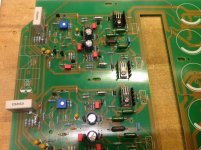
I tested the pots on my PCB, and one of them was already defective. Good finding howarthcd! I replaced them with good quality Bourns pots. You could see that I also replaced the tantalum input caps with Evox MMK 😉
The is no LM317 for the preamp either. I'll use a discrete Jung regulator.
The is no LM317 for the preamp either. I'll use a discrete Jung regulator.
Attachments
Could it be possible that the trimmer, if open circuit, was making the amp more susceptible to interference pickup which led to instability? The channels do have a common 0V.
Seems unlikely. C3 (the Vbe multiplier cap) keeps the impedance relatively low which makes noise pickup less likely.
I've never heard of instability causing a 50 Hz hum.
Anyway, good spot on the trimmer problem. I have some "Bonens" trimmers - to be used with caution!! You would have thought "Buorns" or "Bournes" would have been closer 🙂
http://www.farnell.com/datasheets/727135.pdf
http://www.onsemi.com/pub_link/Collateral/BC237-D.PDF
I noticed BC550C has a base spreading resistance graph that is identical to BC237 ( 160 R @ 1mA ), The 550C must be lower to get the noise figures if does. The 550 seems to be selected grade and should better the BC237. I haven't done the calcualtion but suspect it is about 0.9 nV per root Hz. The BC337 about 0.6 nV. The input resistors could adjusted to better suit. The input resistor will degrade the noise from a low of 0.6dB to a high of about 8 dB. The shunting effect of the preamp will almost take the noise down to the lower value. The BC550C seems to be nearer 0.6 nV. 0.6 nV is about as good as it gets. I suspect BC237 and BC549 are the same device internally. There are slight variations in spec. I wonder if that was test sample alone? If Naim used the lower voltage device it has to be that they selected their own? No way would they risk it otherwise. NOR SHOULD YOU. I have real doubts about this. Has someone in history mis read a BC237?
BC237 gives both Vceo and Vces. It sort of implies the device can see 50 V . I suspect BC550C is about the same.
Below is an interesting list. It seems to me to say BC560C is the outstanding device.
ftp://ece.buap.mx/pub/manuales/Smal Signal.pdf
I tested the pots on my PCB, and one of them was already defective. Good finding howarthcd! I replaced them with good quality Bourns pots. You could see that I also replaced the tantalum input caps with Evox MMK 😉
The is no LM317 for the preamp either. I'll use a discrete Jung regulator.
Looks good so far! What led you to pick the Evox MMK capacitors over the tantalums?
Also which series Bourns pots did you use to get the correct pin spacing?
LTPs not populated yet? 😉
Last edited:
BC560 is a typo. It's what I use on my PNP designs ( I really must buy a few hundred of them and similar as it must be the last chance saloon ) . It is an " outstanding " device as PNP's have slightly better noise it is said. The big league amp designers will probably be more interested in input noise than you would ever guess.
BC560 is a typo. It's what I use on my PNP designs ( I really must buy a few hundred of them and similar as it must be the last chance saloon ) . It is an " outstanding " device as PNP's have slightly better noise it is said. The big league amp designers will probably be more interested in input noise than you would ever guess.
Lucky then that I have 200 off BC550C and BC560C each. Busy stockpiling some transistors.
Unfortunately I can't get KSC3503E anymore, only KSC3503D. Yet I can get lots of KSA1381E, but no KSA1381D. How does that work? Surely with a complementary pair you would expect the manufacturers to be able to supply complementary devices in the same gain band.
Then there are the fakes! They are not rare. A 2N5551 can pretend to be a 2SD756 and the 2N5401 the 2SB716. They will work and can be made pin compatible in the fakes. I have some, they read 170 on my tester whilst real ones read 450. One only hopes they did use 2N5551 and 5401 as the voltage is an issue. I doubt they are MPSA42/92 as they read 100. The fakes look 100% correct with the long T092 package.
http://www.farnell.com/datasheets/727135.pdf
http://www.onsemi.com/pub_link/Collateral/BC237-D.PDF
BC237 gives both Vceo and Vces. It sort of implies the device can see 50 V . I suspect BC550C is about the same.
Below is an interesting list. It seems to me to say BC560C is the outstanding device.
ftp://ece.buap.mx/pub/manuales/Smal Signal.pdf
The list is interesting. On page 10 the voltage rating for BC239 is given as 45 the same as BC237 however the values are in terms of V(BR) CEO as distinct from V CEO. On the other hand the datasheet gives 25 minimum BC239 and 45 minimum BC237. Check this link out. https://www.jedec.org/standards-doc...collector-emitter-base-open-vbrceo formerly b
Avondale uses the MMK in their NAP140 kit board, and it is also mentioned on some Naim upgrade forums...
SB
SB

Here is a concept. The 6 x BC550C is just to show one of the more unlikely upgrades. If the transisors are reasonably matched for gain and Vbe this can work. It isn't too important that one device flows slightly more current. In more specialised applications emitter resistors would be needed ( Naim MC stages ). If for no other reason it ensures there is an equal current flow. A test rig could be built to test that ( 10R and Vre, none used when installed ) . Fitting emitter resistors slightly defeats the object of the modification. All the bases, collectors and emitters are joined. DC offset would double at a guess. A very fair trade for a sweeter sound.
Of more interest is modifying 4K7 to 1K at the input. 1N5 brings the filtering to about the same time constant. It is well worth playing with the combinations to see what suits you best. The Naim preamps were filtered so these kits will not be optimum combined with an unknown source.
I am on my standby computer so have drawn this anew. The circuit is just one of many and only to show LTP. It isn't a prefered one.
not quite.If for no other reason it ensures there is an equal current flow.
If one has identical transistors with identical emitter resistors and the junctions are at identical temperatures then equal currents will flow in the paralleled transistors.
But if the temperatures are not identical and/or the transistors are not identical then adding identical emitter resistors CANNOT ensure that equal currents will flow.
The added emitter resistors reduce the current error. They do not eliminate the current error.
As one increases the value of the emitter resistors, then the attenuation of the error increases. There would come a point where the resistor values are high enough that they alone would so dominate the current flow that identical emitters resistors would get so close to identical currents that one would have acheived the objective, except that the ultra high emitter resistors would prevent the circuit from working as a head amplifier.
This is a feature that gets mentioned occassionaly in power amplifiers.Of more interest is modifying 4K7 to 1K at the input. 1N5 brings the filtering to about the same time constant. It is well worth playing with the combinations to see what suits you best. The Naim preamps were filtered so these kits will not be optimum combined with an unknown source.
The source impedance seen by the input transistors has a significant bearing on the amplifier's stability.
There is a strong correlation for: good stability equals low source impedance.
A lower value series resistor combined with a higher value of grounding capacitor presents a lower source impedance, even though the RF attenaution would be identical.
Going in the opposite direction: high series resistor and low grounding capacitor can invoke instability, or at the least reduce the stability margins.
Apparently one must not go too far with this, some amplifiers do not take kindly to ultra low source impedance. I wish I had sufficient knowledge to recognise those that don't like ultra low source impedance.
Q.)
Can anyone offer some empirical rule to help me?
Last edited:
The list is interesting. On page 10 the voltage rating for BC239 is given as 45 the same as BC237 however the values are in terms of V(BR) CEO as distinct from V CEO. On the other hand the datasheet gives 25 minimum BC239 and 45 minimum BC237. Check this link out. https://www.jedec.org/standards-doc...collector-emitter-base-open-vbrceo formerly b
It was the same in the 1984 version of the book, image attached:
https://ia801703.us.archive.org/32/items/MotorolaSmallSignalTransistorDataBook1984/MotorolaSmallSignalTransistorDataBook1984.pdf
Why the discrepancy?
I would assume that if it was an error then this would have been corrected by REV 6 and certainly not carried through for at least 13 years.
I've seen mention that Naim uses the 2N5089 as a replacement for the BC239C, although I don't know which products this applies to. For the 2N5089 V(BR)CEO is listed as being 25V.
Attachments

Last edited:
It amounts to the same thing with the proviso made. If the transistors are gain matched and Vbe matched the fitting of the emitter resistors in a test rig would be enough to do the better matching possible within this concept. If no care is taken then it is doubtful it will work better. The choice of 2 x BC550C seems prime.
I never really gave it much thought above that. My main point being the text book examples I suspect would never recomend this example I gave. Taking every reasonable care we can, it will work. If there is another test we might do, it would be intesting. One could use 1R and an op amp to give a gain of 100 on the test rig. 1R is very close to reality.
The temperature ideals might be possible due to being bonded together. Point taken about the many other factors. As you say the emitter swamping resistor needs to be significant to force what is hoped for. That then defeats the ideal being pursued. Naim used 15R for the MC stage ( 5 transistors in paralell ). I doubt it was a great idea. I guess 5 x 100 R divided by 5 is 20 R crudely put ( and not how it is said to work ) . 5 x perhaps 120 R will be 24 R. Maybe it is not so bad? Noise theory is not taught this way. It seems to reasonably work. I dare say coincidence and not fact. From this we can see the 4K7 of the input resistor is not a good thing. 1K seems to be not too bad on op amp charts. Even 220R and 6n8 looks OK. If you go lower sometimes a PSU hum loop appears ( it is not really a fault ). That would take until Christmas to discuss so best to say it can.
My bigger point was doing the unthinkable is mostly the better choice.
This is a feature that gets mentioned occassionaly in power amplifiers.
The source impedance seen by the input transistors has a significant bearing on the amplifier's stability.
There is a strong correlation for: good stability equals low source impedance.
A lower value series resistor combined with a higher value of grounding capacitor presents a lower source impedance, even though the RF attenaution would be identical.
Going in the opposite direction: high series resistor and low grounding capacitor can invoke instability, or at the least reduce the stability margins.
Apparently one must not go too far with this, some amplifiers do not take kindly to ultra low source impedance. I wish I had sufficient knowledge to recognise those that don't like ultra low source impedance.
Q.)
Can anyone offer some empirical rule to help me?
Douglas Self seems to have covered this. I respect your point Andrew as you might be offering the right caution. My gut reaction is 330pF are beautiful cheap devices. The time constant is 1.6 uS if my brain is in gear? Equally so it is about 100 kHz. That feels about right. The idea being Radio both is audibal and a source of unexspected distortion . It can cause DC offset in a very unpleasent way. This is the terrible bandwidth limiting horrible English amplifiers have. Lies , dam lies and hi fi lies ?
I always add 2uS passive filters to my phono stages. It allows me the sound of all passive with many active advatages. Don't let anyone tell you all passive is better. Matamatically it isn't. I use 75uS passive and 3180/318 active with 220R and 10 nF output. The 220R also brakes the PSU chain and offers protection. 220R is low enough not to be a serrious noise source.
KSC1845FTA | Fairchild KSC1845FTA NPN Bipolar Transistor, 50 mA, 120 V, 3-Pin TO-92 | Fairchild Semiconductor
KSC1845 comes up with intersting figures. It is a little hard to relate it's noise figures to others. The output capacitance looks best of type. It isn't exactly any Japanese tranistor I know of. I suspect it is one they sell as their own. Centre collector.
It was suggested that all transistor be handled as if static sensetive and a reveresed bias diode coneceted base to emitter. 1N4148 I guess?
http://www.lite8.com/download/2SC1845.pdf
Presuming the same the device looks ideal for a NAP140. Even likes Naims source resistance if 500mA and 4K7 ( near enough ). For once given as a graph. As far as I can see it is the same device.

Presuming the same the device looks ideal for a NAP140. Even likes Naims source resistance if 500mA and 4K7 ( near enough ). For once given as a graph. As far as I can see it is the same device.
I have looked at lot's of those noise graphs and tried to work out what they are telling me.
Many tell us that the NF figure of merit is ONLY of use for Radio Frequency duty.
Here's how I read the noise graph and try to adopt the result to an audio frequency duty.
Follow the red line which is at ~0.55mA of Ic.
where it meets the 3dB curve is opposite the 400r level for Rg.
Does that mean that the total noise of the transistor PLUS the 400r of Rg, gives a noise that is 3dB worse than a 400r resistor alone?
Should i just stop there and compare other transistor to that 3dB @ 400r of Rg to find one that is quieter/louder?
Can I go further?
Since a 1k resistor has the equivalent of 4nV/rtHz for the audio band, then a 400r resistor will have about 2.5nV/rtHz
Does that mean the transistor plus 400r has an equivalent noise of (2.5/07071)nV/rtHz
i.e. ~ 3.5nV/rtHz?
Can we extend that to some other value for the actual Rg that the transistor sees?
Last edited:
- Home
- Amplifiers
- Solid State
- NAP-140 Clone Amp Kit on eBay