Yeah i have been trying to find a peice of ally or copper big enough to try and make a sort of 2 box setup . No luck yet!
The other issue being that the PSu board is just a little to long to divide it up properly which is annoying.
Also yeah your right i will send all the 0v (boards, speaker neg etc.) back to the cap board output, though i might keep the input phono gnd to the boards since i have heard this is better.
The other issue being that the PSu board is just a little to long to divide it up properly which is annoying.
Also yeah your right i will send all the 0v (boards, speaker neg etc.) back to the cap board output, though i might keep the input phono gnd to the boards since i have heard this is better.
Sorry yes thats right, just the four biggies back to the cap centre.
Also seen as you are not dual mono, you might get much of the effect by beefing up the 2 caps on the amp boards themselves.
They are probably 100uf at 63v? Try for a little bigger and higher voltage for a couple of quid, BEST quality you can get, something like ZL/FC/NHG 100v
Also seen as you are not dual mono, you might get much of the effect by beefing up the 2 caps on the amp boards themselves.
They are probably 100uf at 63v? Try for a little bigger and higher voltage for a couple of quid, BEST quality you can get, something like ZL/FC/NHG 100v
They are currently 220uf 50v Nichicon Fine Gold as supplied with the kit, which is already twice what the Ncc200 have. Think i should go higher?
No then, but there is something you can try once you are all done and you have run it for two weeks. I'll leave you to work out or find out what it is 😉

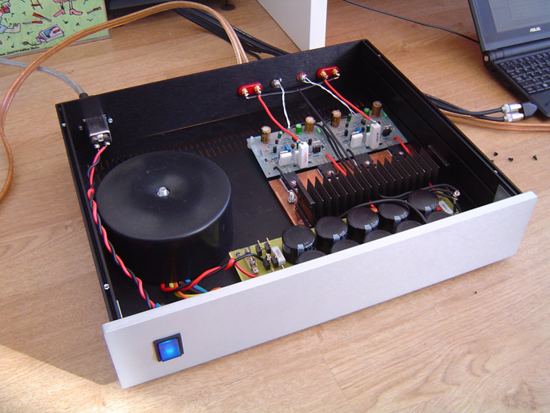
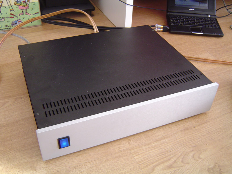
If anyone is interested here is my finished build using the earlier nc200 type boards. I need to let them bed in a bit but they sounds pretty damn good as they are. Seem a lot more detailed than the LM3886 based amp i have used before. In fact quite a lot like a higher power more muscular T-amp in character. Very nice indeed though i feel they might need a bit of time to reveal there true character.
A very worth while build.
A very worth while build.
An externally hosted image should be here but it was not working when we last tested it.
An externally hosted image should be here but it was not working when we last tested it.
Fill showing off again i see 
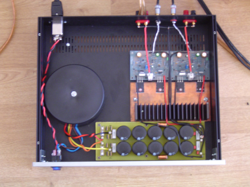
Never noticed before, am I right in saying the two speaker returns go to a Tee point and then share a single conductor back to the caps.
If so you want to change it for two beefy wires all the way back to the caps for an improvement. some 4mm speaker cable from the bay will do it.
Never noticed before, am I right in saying the two speaker returns go to a Tee point and then share a single conductor back to the caps.
If so you want to change it for two beefy wires all the way back to the caps for an improvement. some 4mm speaker cable from the bay will do it.
Sounds like a good idea. I will give that a go some time. I am currently using 2.5mm solid core cable wich i really like using cos it stays where you bend it. It's funny the input cable is solid core solid silver /teflon insulated from home grown audio and output Pirelli 2.5mm from a twin and earth roll. It might sounds illy the difference in price but this si some great looking cable, easy to work with and i recon its just the job for high current stuff like speaker outputs and psu wiring.
I also don't like multistrand much at all for anything since is always corrodes so much quicker which must degrade performance over time. I have some oldish speaker cable with a transparent insulator and the stuff goes really tarrnished for about 6 inches up the cable from where you cut it in jus a couple of years.
Sorry my thoughts on cable, i will do that individual return trick when i get some time off.
The amp sounds better today, yesterday the detail seems amazing but i dunno it seemed a littel muddled as the music got into a complicated section. That seems to have really cleared up now, its an absolute beast of an amp for classic rock. Sabbath, Zepplin Ac/Dc sound so rich through it, though i must try something a little lighter to see what its like on more delicate material.
Of course its rock beast, right in its era, sort of 😉
Just do the two wire thing anyway, wont take you 15 minutes will it?
Now you just need to build another one and go active
Just do the two wire thing anyway, wont take you 15 minutes will it?
Now you just need to build another one and go active
Yeah i will do the mod when a get a spare few minutes.
I doubt i will be doing many project for a while.
I promised she who must be obeyed it was last 2 channel amp.
I doubt i will be doing many project for a while.
I promised she who must be obeyed it was last 2 channel amp.
ground bus
The PSU board looks nice. Did you send away to have it etched or did you do the etching yourself?
Some thoughts based on my limited experience:
If you flip your binding posts around you could put your Ground bus (star) at the speaker terminals. This is how Naim does it, I believe. That would allow you a very short run for your signal ground to the star. In my last LM based GC I had very short separate runs for the signal ground to star and that made a nice difference.
As for snubbers, they seem to work some places and not others. They can really add some speed to the presentation in some applications or, they can really F the whole thing up in others. I built a snubberized PS for a pair of UcD180 that really didn't work. Much better with snubbers yanked out. On the GC amps I've built, I think a good quality 100nF polycap across the leads from the transformer just before the rectifiers really helps. As always, play around with it and find out what sounds best.
To quote George Clinton: "as my good friend James brown once said, "ain't nothin' good if you don't play with it.'"
Hi,
Yeah i designed and etched the PSU board myself. Idesigned it so i can quite quickly swap out components such as the snubbers and inductors. I think i will levae it a couple for weeks before changing anything apart from the grounding which i will when i get time.
Thanks for the advice on that.
Yeah i designed and etched the PSU board myself. Idesigned it so i can quite quickly swap out components such as the snubbers and inductors. I think i will levae it a couple for weeks before changing anything apart from the grounding which i will when i get time.
Thanks for the advice on that.
Force is correct, between two negatives is how Naim do it but the conventional wisdom is to the caps is better.
I have to say on my layout the caps seem like the better way of doing it. I think i am gonna simply send back individual runs from the speaker posts to the the cap center.
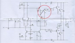
Polarity of DC blocking input capacitor
Further to an earlier post, does everyone agree that the input blocking cap (C1) and the NFB DC blocking cap (C5) are shown reverse biased?
It seems to me, that to get any bias current into Q1, a current must flow from ground via R2 & R3. This will make the voltage at the junction of R2 & R3 negative with respect to ground. That being so, the voltage across C1 when there is no signal will be the same negative voltage with respect to the input pin i.e. the cap is shown negatively biased.
With Q2, the bias current must come from the speaker output - which we hope is at 0V. Therefeore the voltage at the base of Q2 will be negative with respect to ground. Therefore, c5 is also shown negatively biased.
Can somebody confirm (or deny) my logic before I build my new amps?
Thanks for any help.
Just got my kit .
I got pretty blue boards (NAP140C version) but did not get the toshiba transistors...
my transistors look very similar to the ones in post #7 of this thread and are labeled as follows.
SK
C2837
7N P
Does anyone know if these will work? Are they are equivalent tosh transistors that have been coming with these kits?
thanks
Re: Polarity of DC blocking input capacitor
hi cdswift,
I had noticed the feedback cap was opposite to what I expected. There are 3 different "NAP" schematics with the cap this way and I found one that had it the "correct" way. From what I understand, there is only a very small voltage across it, so it isn't a big problem until a fault occurs.
I also reckon the 27R resistor in the Vbias circuit is in the wrong position if Douglas Self is to be believed. What do you think?
regards
cdswift said:Further to an earlier post, does everyone agree that the input blocking cap (C1) and the NFB DC blocking cap (C5) are shown reverse biased?
It seems to me, that to get any bias current into Q1, a current must flow from ground via R2 & R3. This will make the voltage at the junction of R2 & R3 negative with respect to ground. That being so, the voltage across C1 when there is no signal will be the same negative voltage with respect to the input pin i.e. the cap is shown negatively biased.
With Q2, the bias current must come from the speaker output - which we hope is at 0V. Therefeore the voltage at the base of Q2 will be negative with respect to ground. Therefore, c5 is also shown negatively biased.
Can somebody confirm (or deny) my logic before I build my new amps?
Thanks for any help.
hi cdswift,
I had noticed the feedback cap was opposite to what I expected. There are 3 different "NAP" schematics with the cap this way and I found one that had it the "correct" way. From what I understand, there is only a very small voltage across it, so it isn't a big problem until a fault occurs.
I also reckon the 27R resistor in the Vbias circuit is in the wrong position if Douglas Self is to be believed. What do you think?
regards
Re: Re: Polarity of DC blocking input capacitor
You're right!
Correct wiring attached.
I also reckon the 27R resistor in the Vbias circuit is in the wrong position if Douglas Self is to be believed. What do you think?
You're right!
Correct wiring attached.
Attachments
Re: Polarity of DC blocking input capacitor
Thanks for the response - this concurs with my view.
I am not sure what Douglas Self has to say about the position of bias resistor 27R.
However, it looks OK to me as it limits the collector current of Q5 and provides some element of negative feedback to keep the voltage across this bit of the circuit stable.
Regards
Chris Swift
- Home
- Amplifiers
- Solid State
- NAP-140 Clone Amp Kit on eBay