There are extra TIP41C in the KIT. You can repalce the Q5 by TIP41C and mount the TIP41C on the heat sink. Then quiescent current per output transsistor can be 10 - 20mA!
True, but if it were a Naim original a lot of folks sould set it to 36-40 and no more.
As said, set it to 38 and leave it on for about 20 mins, over which time it will drift a little, then adjust.
The guy did say "The quiescent current should be 1 to 5mA per power transistor" ... we are talking the whole thing should be set to 38mA.
Hows it doing Phil?
As said, set it to 38 and leave it on for about 20 mins, over which time it will drift a little, then adjust.
The guy did say "The quiescent current should be 1 to 5mA per power transistor" ... we are talking the whole thing should be set to 38mA.
Hows it doing Phil?
Actually depends which it you are talking about. The initial kit was a direct copy of the ncc200 with a few component changes. The second version is much closer to an original Naim design.
Mine is the original kit.
Mine is the original kit.
Hey Brian,
Very well, my chassis arrived from hifi2000 and i have and started thinking about mounting it all. Also waiting for my caps to arrive from ebay for my Cap 10. Still umm and arring about whether to use ultra fast but soft diodes or standard decent metal packaged bridges.
Very well, my chassis arrived from hifi2000 and i have and started thinking about mounting it all. Also waiting for my caps to arrive from ebay for my Cap 10. Still umm and arring about whether to use ultra fast but soft diodes or standard decent metal packaged bridges.
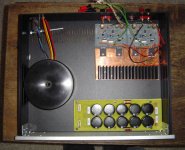
Layout A has the advantage of short interconnect leads while B has the heatsink between the Amp boards and the tranny.
Any advice ?
Oh yeah and before nayone asks the yes my diodes arent on board yet. 16Amp Hexfreds in the post though so hopefully it will be ok
Any advice ?
Oh yeah and before nayone asks the yes my diodes arent on board yet. 16Amp Hexfreds in the post though so hopefully it will be ok
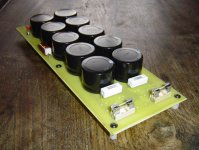
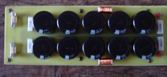
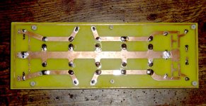
PSU is 5 x 6800 uf (Elna LP5) per rail, using dual fullwave recifiers made from Hexfred diodes.
Near the end of the cap bank there are small inductors handwound around 3r3 resistors, at the end are 100nf wimas, then a snubber made from a 0r47 resistors and 1n5 caps.
All could be remove to just leave a standard setup but i though i would start with these in place and try removing each part to see how it effects the sound.
Regards,
Phil
sound?
Sorry to butt in here,
I was just considering weather to build up a second, more sophisticated LM3875 amp or get a a pair of these boards.
Any impressions on the sound? I have always liked the Naim sound but I thought my dual-mono LM3875 sounded better than my friend's old NAP110.
Anyone have a finished build they would care to review here?
I have had them up and running and also have a few LM based amps. The chippamp.com Lm3886 and the My Ref C design as well.
In the next few days they should be finished and replace the gainclone and them we will see. The one issue is mine are the Avondale ncc200 copies rather than the straight Nap140 boards that they now sell so it won't be strictly comparable. I would however hope that a well built and pair of either with a decent psu could top the gainclones, else i won't have bothered!!
In the next few days they should be finished and replace the gainclone and them we will see. The one issue is mine are the Avondale ncc200 copies rather than the straight Nap140 boards that they now sell so it won't be strictly comparable. I would however hope that a well built and pair of either with a decent psu could top the gainclones, else i won't have bothered!!
Phil,
Loooking very good, credit to you.
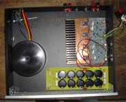
Gives a pic of the underside of the PSU. Only thing you might change is to make it dual mono - but you could do that if you think its heading where you like it.
Nice one,
Brian
Loooking very good, credit to you.
Gives a pic of the underside of the PSU. Only thing you might change is to make it dual mono - but you could do that if you think its heading where you like it.
Nice one,
Brian
To be honest your probably right about the dual mono being a better idea, but the caps came as a lot of 10 from ebay so i either lost a couple and went like that or did a mono psu with 68,000 uf. Plus i had the option of one pretty good tranny or 2 less good ones. Its the start of the year, I am self employed so what with the tax man i am skint.
Hopefully the high capacitance and 500va should keep it pretty stiff anyway.
Here the board layout and thanks for the support.
Phil
Hopefully the high capacitance and 500va should keep it pretty stiff anyway.
Here the board layout and thanks for the support.
Phil
Attachments
Any suggestions on layout as well, recon shorter leads would be better than the heatsink as a barrier?
No thanks needed, I havent helped that much, more encouragement.
One big tranny can often be better than two small ones, only two big ones win 😉
Its going to be a top notch amp on budget, psu looks good, did you calculate the inductor off the web calculator?
Whats the gauge of the enamelled wire?
Nice job on the DIY board, wish I could do that.
One big tranny can often be better than two small ones, only two big ones win 😉
Its going to be a top notch amp on budget, psu looks good, did you calculate the inductor off the web calculator?
Whats the gauge of the enamelled wire?
Nice job on the DIY board, wish I could do that.
I'd go with whats easier to wire, I believe its the vertical direction you worry about most with Toroidals (ie the next component above seperated by a few inches), though could be correct.
As long as theres some space I'd go with easy to build any time, shortest returns from speaker to caps. Ie put the toroid at the front if you can so the speaker returns get back to the cap with least resistance.

As long as theres some space I'd go with easy to build any time, shortest returns from speaker to caps. Ie put the toroid at the front if you can so the speaker returns get back to the cap with least resistance.
To be honest its a bit of a pick n mix PSU nicking all the stuff i have used and or heard about.
The snubber network seems to be a pretty standard setup used on a lot of DIYaudio boards since CarlosFM came up with it for the LM3886 based gainclones. Seem it used on several other setups.
The inductor setup is based on the DXamp which i have been keeping an eye on. Its also uses the same snubber network values. The board is very heavily built so i can unsolder stuff at will and short them out to see if that changes things for the better.
My pcb layout skills aint bad but the psu is in truth a bastard child of many things. Mainly cos i cant work out that Duncan amp PSU simulator for toffee, i studied at art college instead of continuing electronics unfortunately.
We will see.
You should try something like Eagle PCB software though, i built my first pcb in about a day using it.
- Home
- Amplifiers
- Solid State
- NAP-140 Clone Amp Kit on eBay